RETURN
VALVE
PUMP
LEFT TURN | STRAIGHT AHEAD | RIGHT TURN |
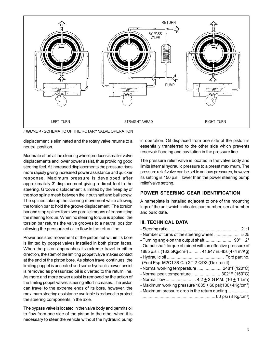
FIGURE 4 - SCHEMATIC OF THE ROTARY VALVE OPERATION
displacement is eliminated and the rotary valve returns to a neutral position.
Moderate effort at the steering wheel produces smaller valve displacements and lower power assist, thus providing good steering feel. At increased displacements the pressure rises more rapidly giving increased power assistance and quicker response. Maximum pressure is developed after approximately 3' displacement giving a direct feel to the steering. Groove displacement is limited by the freeplay of the stop spline mesh between the input shaft and ball screw. The splines take up the steering movement while allowing the torsion bar to hold the groove displacement. The torsion bar and stop splines form two parallel means of transmitting the steering torque. When no steering torque is applied, the torsion bar returns the valve grooves to a neutral position allowing the pressurized oil to flow to the return line.
Power assisted movement of the piston nut within its bore is limited by poppet valves installed in both piston faces. When the piston approaches its extreme travel in either direction, the stem of the limiting poppet valve makes contact at the end of the piston bore. As piston travel continues, the limiting poppet is unseated and some hydraulic power assist is removed as pressurized oil is diverted to the return line. As more and more power assist is removed by the action of the limiting poppet valves, steering effort increases. The piston can travel to the extreme ends of its bore, however, the maximum steering assistance available is reduced to protect the steering components in the axle.
The bypass valve is located in the valve body and permits oil to flow from one side of the piston to the other when it is necessary to steer the vehicle without the hydraulic pump
in operation. Oil displaced from one side of the piston is essentially transferred to the other side which prevents reservoir flooding and cavitation in the pressure line.
The pressure relief valve is located in the valve body and limits internal hydraulic pressure to a preset maximum. The pressure relief valve can be set to various pressures, however its setting is 150 p.s.i. lower than the power steering pump relief valve setting.
POWER STEERING GEAR IDENTIFICATION
A nameplate is installed adjacent to one of the mounting lugs of the unit which indicates part number, serial number and build date.
III. TECHNICAL DATA
- Steering ratio | 21:1 |
- Number of turns of the steering wheel | 5.25 |
- Turning angle on the output shaft | 90° + 2° |
- Output shaft torque obtained with an effective pressure of
1885 p.s.i. (132.5Kg/cm2) | 41,947 |
- Hydraulic oil | Ford part no. |
(Ford Esp. M2C1 | |
- Normal working temperature | .................... 248°F(120°C) |
- Normal peak temperature | 302°F (150°C) |
- Normal flow | 4.2 + 2 G.P.M. (16 + 1 L/m) |
-Maximum working pressure 1885 + 60 psi(130+4Kg/cm2)
-Maximum pressure drop in the return ducting .................
............................................................. 60 psi (3 Kg/cm2)
5