3.Disconnect the steering column at the input shaft following the vehicle manufacturer’s instructions.
4.Disconnect the pitman arm from the vehicle’s steering linkage using the vehicle manufacturer’s instructions.
CAUTION: If it is necessary to remove the pitman before the steering gear can be removed from the vehicle, DO NOT USE HEAT OR POUND ON THE PITMAN ARM OR OUTPUT SHAFT as damage can result. Do not attempt repairs to these components. They must be replaced if damaged. Use a large gear puller to remove the pitman arm such as
5.Remove the steering gear from the vehicle.
VII. SPECIAL TOOL REQUIREMENTS
The following special tools are required to disassemble and assemble the power steering gear.
297661 Spanner Wrench - Used to remove and replace the valve nut.
297676 Seating Tool - Used to assure seating and prevent damage to the teflon glide seal rings in the valve nut during reassembly.
297674 Piloted Seal Tool - Used to seat the seal and spacer in the body of the power steering gear.
297675 Piloted Seal Tool - Used to seat the seal in the end cover.
297660 Poppet Wrench - Used to remove and install limiting valve poppets.
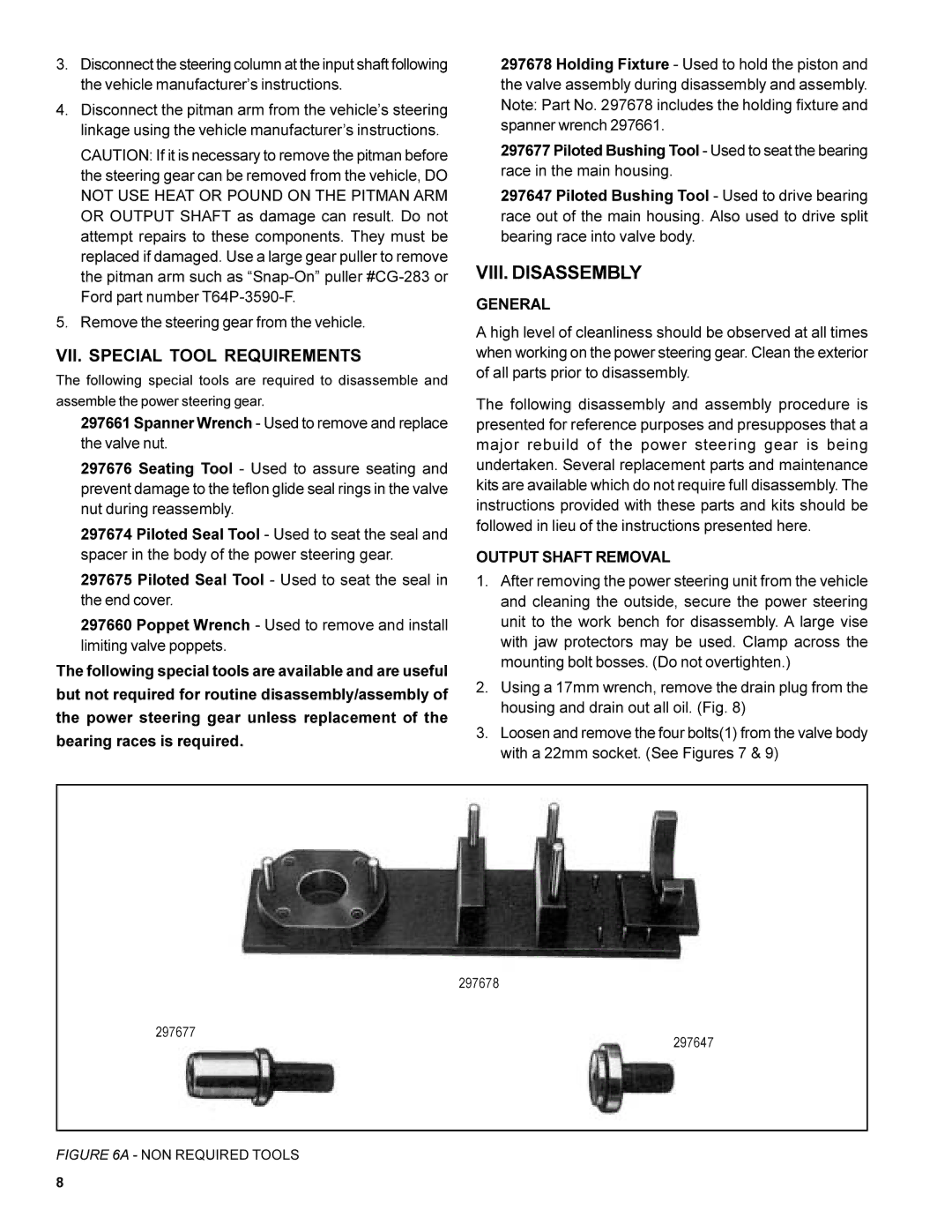
The following special tools are available and are useful but not required for routine disassembly/assembly of the power steering gear unless replacement of the bearing races is required.
297678 Holding Fixture - Used to hold the piston and the valve assembly during disassembly and assembly. Note: Part No. 297678 includes the holding fixture and spanner wrench 297661.
297677 Piloted Bushing Tool - Used to seat the bearing race in the main housing.
297647 Piloted Bushing Tool - Used to drive bearing race out of the main housing. Also used to drive split bearing race into valve body.
VIII. DISASSEMBLY
GENERAL
A high level of cleanliness should be observed at all times when working on the power steering gear. Clean the exterior of all parts prior to disassembly.
The following disassembly and assembly procedure is presented for reference purposes and presupposes that a major rebuild of the power steering gear is being undertaken. Several replacement parts and maintenance kits are available which do not require full disassembly. The instructions provided with these parts and kits should be followed in lieu of the instructions presented here.
OUTPUT SHAFT REMOVAL
1.After removing the power steering unit from the vehicle and cleaning the outside, secure the power steering unit to the work bench for disassembly. A large vise with jaw protectors may be used. Clamp across the mounting bolt bosses. (Do not overtighten.)
2.Using a 17mm wrench, remove the drain plug from the housing and drain out all oil. (Fig. 8)
3.Loosen and remove the four bolts(1) from the valve body with a 22mm socket. (See Figures 7 & 9)
297678
297677
297647
FIGURE 6A - NON REQUIRED TOOLS
8