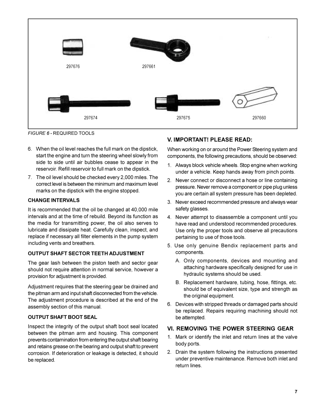
297676 | 297661 |
297674 | 297675 | 297660 |
FIGURE 6 - REQUIRED TOOLS
V. IMPORTANT! PLEASE READ:
6.When the oil level reaches the full mark on the dipstick, start the engine and turn the steering wheel slowly from side to side until air bubbles cease to appear in the reservoir. Refill reservoir to full mark on the dipstick.
7.The oil level should be checked every 2,000 miles. The correct level is between the minimum and maximum level marks on the dipstick with the engine stopped.
CHANGE INTERVALS
It is recommended that the oil be changed at 40,000 mile intervals and at the time of rebuild. Beyond its function as the media for transmitting power, the oil also serves to lubricate and dissipate heat. Carefully clean, inspect, and replace if necessary all filter elements in the pump system including vents and breathers.
OUTPUT SHAFT SECTOR TEETH ADJUSTMENT
The gear lash between the piston teeth and sector gear should not require attention in normal service, however a provision for adjustment is provided.
Adjustment requires that the steering gear be drained and the pitman arm and input shaft disconnected from the vehicle. The adjustment procedure is described at the end of the assembly section of this manual.
OUTPUT SHAFT BOOT SEAL
Inspect the integrity of the output shaft boot seal located between the pitman arm and housing. This component prevents contamination from entering the output shaft bearing and retains grease on the bearing and output shaft to prevent corrosion. If deterioration or leakage is detected, it should be replaced.
When working on or around the Power Steering system and components, the following precautions, should be observed:
1.Always block vehicle wheels. Stop engine when working under a vehicle. Keep hands away from pinch points.
2.Never connect or disconnect a hose or line containing pressure. Never remove a component or pipe plug unless you are certain all system pressure has been depleted.
3.Never exceed recommended pressure and always wear safety glasses.
4.Never attempt to disassemble a component until you have read and understood recommended procedures. Use only the proper tools and observe all precautions pertaining to use of those tools.
5.Use only genuine Bendix replacement parts and components.
A.Only components, devices and mounting and attaching hardware specifically designed for use in hydraulic systems should be used.
B.Replacement hardware, tubing, hose, fittings, etc. should be of equivalent size, type and strength as the original equipment.
6.Devices with stripped threads or damaged parts should be replaced. Repairs requiring machining should not be attempted.
VI. REMOVING THE POWER STEERING GEAR
1.Mark or identify the inlet and return lines at the valve body ports.
2.Drain the system following the instructions presented under preventive maintenance. Remove both inlet and return lines.
7