3 | 4 | 5 | 6 | 7 | 8 | 9 | 10 | 11 | 12 |
FIGURE 28
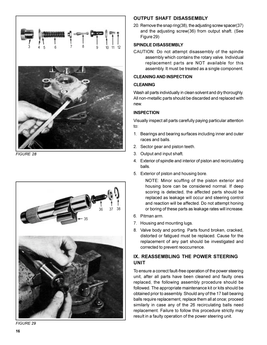
36 37 38
35
FIGURE 29
OUTPUT SHAFT DISASSEMBLY
20.Remove the snap ring(38), the adjusting screw spacer(37) and the adjusting screw(36) from output shaft. (See Figure 29)
SPINDLE DISASSEMBLY
CAUTION: Do not attempt disassembly of the spindle assembly which contains the rotary valve. Individual replacement parts are NOT available for this assembly. It must be treated as a single component.
CLEANING AND INSPECTION
CLEANING
Wash all parts individually in clean solvent and dry thoroughly. All
INSPECTION
Visually inspect all parts carefully paying particular attention to:
1.Bearings and bearing surfaces including inner and outer races and balls.
2.Sector gear and piston teeth.
3.Output and input shaft.
4.Exterior of spindle and interior of piston and recirculating balls.
5.Exterior of piston and housing bore.
NOTE: Minor scuffing of the piston exterior and housing bore can be considered normal. If deep scoring is detected, the affected parts should be replaced as leakage will occur and steering control and reaction will be affected. Do not attempt honing or boring of these parts as leakage rates will increase.
6.Pitman arm.
7.Housing and mounting lugs.
8.Valve body and porting. Parts found broken, cracked, distorted or fatigued must be replaced. Cause for the replacement of any part should be investigated and corrected to prevent reoccurrence.
IX. REASSEMBLING THE POWER STEERING UNIT
To ensure a correct
16