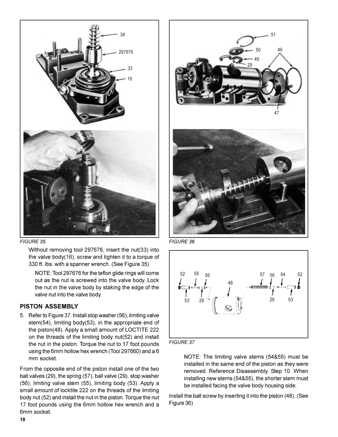
34
297676
33
16
FIGURE 35
Without removing tool 297676, insert the nut(33) into the valve body(16), screw and tighten it to a torque of 330 ft. lbs. with a spanner wrench. (See Figure 35)
NOTE: Tool 297676 for the teflon glide rings will come out as the nut is screwed into the valve body. Lock the nut in the valve body by staking the edge of the valve nut into the valve body.
PISTON ASSEMBLY
5.Refer to Figure 37. Install stop washer (56), limiting valve stem(54), limiting body(53), in the appropriate end of the piston(48). Apply a small amount of LOCTITE 222 on the threads of the limiting body nut(52) and install the nut in the piston. Torque the nut to 17 foot pounds using the 6mm hollow hex wrench (Tool 297660) and a 6 mm socket.
From the opposite end of the piston install one of the two ball valves (29), the spring (57), ball valve (29), stop washer (56), limiting valve stem (55), limiting body (53). Apply a small amount of locktite 222 on the threads of the limiting body nut (52) and install the nut in the piston. Torque the nut 17 foot pounds using the 6mm hollow hex wrench and a 6mm socket.
51
50 46
49
29
47
FIGURE 36
52 | 55 | 56 | 57 | 56 | 54 | 52 |
|
|
| 48 |
|
|
|
53 |
| 29 |
| 29 |
| 53 |
FIGURE 37
NOTE: The limiting valve stems (54&55) must be installed in the same end of the piston as they were removed. Reference Disassembly, Step 10. When installing new stems (54&55), the shorter stem must be installed facing the valve body housing side.
Install the ball screw by inserting it into the piston (48). (See Figure 36)
18