41
40 39
FIGURE 24
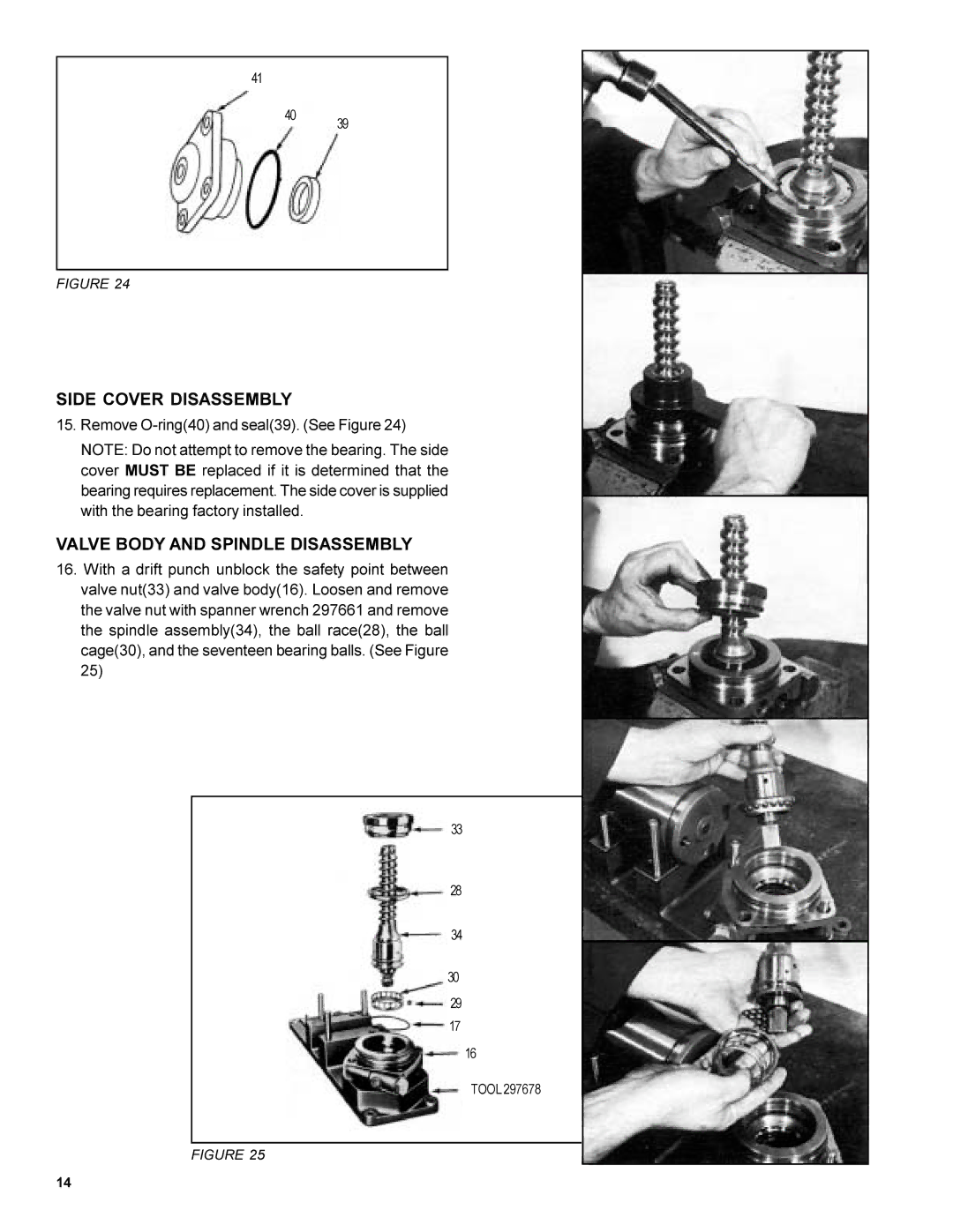
SIDE COVER DISASSEMBLY
15.Remove
NOTE: Do not attempt to remove the bearing. The side cover MUST BE replaced if it is determined that the bearing requires replacement. The side cover is supplied with the bearing factory installed.
VALVE BODY AND SPINDLE DISASSEMBLY
16.With a drift punch unblock the safety point between valve nut(33) and valve body(16). Loosen and remove the valve nut with spanner wrench 297661 and remove the spindle assembly(34), the ball race(28), the ball cage(30), and the seventeen bearing balls. (See Figure 25)
33
28
34
30
29
17
16
TOOL 297678
FIGURE 25
14
