7P RO 7S RO
7P RO, A/C-7S RO
7P RO, A/C-7S RO
7P RO, A/C-7S RO
Trademarks
Contents
7P RO, A/C-7S RO
Specifications
Introduction
Front Panels of the A/C-7 RO
Unpacking
Description of Front Panels
About This User’s Guide
Leds
7P RO, A/C-7S RO
Installation
7P RO, A/C-7S RO
POWER-ON/OFF Sequence
Self-Test Printout for A/C-7P RO
Self-Test Printout for A/C-7S RO
Self-Test Printout for A/C-7S RO,
Self-Test Printout,
Configuration
A/C-7 RO Configuration
Configuration Switch Settings
Output Protocol SW14 SW15 SW16 SW17
SW11 SW14 SW15 SW16 SW17 SW18
Tests/Diagnostic SW11 SW18
SW14 SW15 SW16 SW17
SW21 SW22 SW23
SW26 SW27
SW24
SW25
Serial X-On/X-Off SW28
Host/PC Download Commands
Host/PC Download Command Overview
Host/PC Download Command
Command Number
11 . Host/PC Download Commands
LPI
11. Host/PC Download Commands
Command 3 Characters PER Inch
Command 1 Buffer Size
Command 2 Lines PER Inch
Command 6 Maximum Print Position
Command 4 Line Spacing
Command 5 Form Length
Command 7 Print Case
Command 8 LU1 Language
Font
Command 9 Epson Matrix
Command 11 Paper Path
Command 12 Form Feed Before Local Screen Print
Command 13 Form Feed After Local Screen Copy
Command 15 CR at MPP +
Command 19 FF Valid Location
Command 17 Valid FF Followed by Data
Command 18 Valid FF AT END of Print Buffer
Command 20 Automatic Function AT END of JOB
Command 21 Print Quality FastDraft
Command 27 FF After Time Elapse
Command 25 IBM Motion Commands
Command 26 Suppress Empty Forms
Command 32 Paper Size
Command 30 Override of Formatting Commands
Command 31 TRUNCATE/WRAP Select
Command 37 Vertical Channel Select VCS
Command 34 Intervention Required IR Timeout
Command 36 Suppress IBM Control Codes
Command 38 True LPI Spacing
Command 39 CPT Ending Delimiter Characters
Command 40 CPT Start Delimiter Characters
Command 41 Command ID Character
Command 42 Start and Stop Ebcdic HEX Dump
Command 45 SCS TRN Translate
Command 50 Sharing Port Timeout
Command 51 Host Port Timeout
Command 55 Custom User Strings
Command 56 Parallel Port Initialization String
Command 57 Host Port Initialization String
Command 58 SERIAL-PORT Initialization String
Command 61 Automatic Print Orientation APO
Command 62 Primary Paper Tray Orientation
Command 63 Alternate Paper Tray Orientation
Command 64 Manual Feed Tray Orientation
Command 65 Character SET Selection
Command 70 Overwrite Ebcdic SCS/LU1 Translation Table
Command 71 Overwrite DSC LU3 Translation Table
Command 76 SERIAL-IN Baud Rate
Command 79 SERIAL-IN Parity
Command 77 SERIAL-IN Word Length
Command 78 SERIAL-IN Stop Bits
Command 84 6 LPI String
Command 85 8 LPI String
Command 86 10 CPI String
Command 88 12 CPI String
Command 87 15 CPI String
Command 89 16.7 CPI String
Command 98 Restore Defaults or Print Configuration
Command 99 Store Configuration Permanent Memory
To complete the command, the value 0 must be used
Restoring Factory Defaults
Operation
Printer Sharing
Host Port Initialization
Print Position and Page Length
Laser Printing
17.1
Computer Output Reduction COR
Automatic Print Orientation APO
Printing with the APO Feature
Generic Mode
Other Printer Commands
Command Function
¬TN
Advanced Features
Command Pass-Thru
SCS Mode Transparent Data
Custom User Strings
Bar Code
Color Printing
Printing Bar Codes
Be aware that the table gives rounded values only
Width
Module width in mm inches Epson
7P RO, A/C-7S RO
7P RO, A/C-7S RO
This data overrun by barcode
Code 3
Postnet
EAN
1234
UPC a
123456 789128
0123456789
Code
7P RO, A/C-7S RO
Symbol Character
Value Code a Code B Code C
7P RO, A/C-7S RO
NUL SOH STX ETX EOT ENQ ACK BEL DLE DC1 DC2 DC3
DC4 NAK SYN
O Graphics Language
Iogl Command String
Parameter Description Units Valid
Values
Measurement
Helpful Hints
XY Coordinate System on
End
Start
100,0
100,600
Start 300,300
End 600,600
Center
900,2400
180 Center Start 900,900 500,900
13. Example of Arc
7P RO, A/C-7S RO
14. Color/Shading and Pie Chart
’clock = starting point for first pie segment
15. Segment of Circle
7P RO, A/C-7S RO
16. Bar Chart Histogram
17. Run Line Chart
Text
O Graphics Language Iogl in Action
Sales Calls PER DAY
20. Placement of Bar Chart
104
105
Linking Graphical Output to a Host Application
Printing Images From The Host
108
Troubleshooting
A/C-7 RO Self-Test
Ebcdic Hex Dump
Ascii Hex Dump
Problem Resolution Guide
Problem or Message Probable Cause Action
113
114
115
116
Size
Typeface Symbol Set Orient Pitch Point
Appendix a Font Fgid Reference For HP LaserJet Printers
Table A-1 . Selecting Standard Fonts
119
120
121
122
123
124
125
126
127
128
129
130
131
132
133
134
135
136
137
138
139
140
Appendix B Character Sets
Figure B-1. Roman
Figure B-2. Code
Appendix C Serial-Port Specifications
Figure C-1. Input and Output Connector Pinout
145
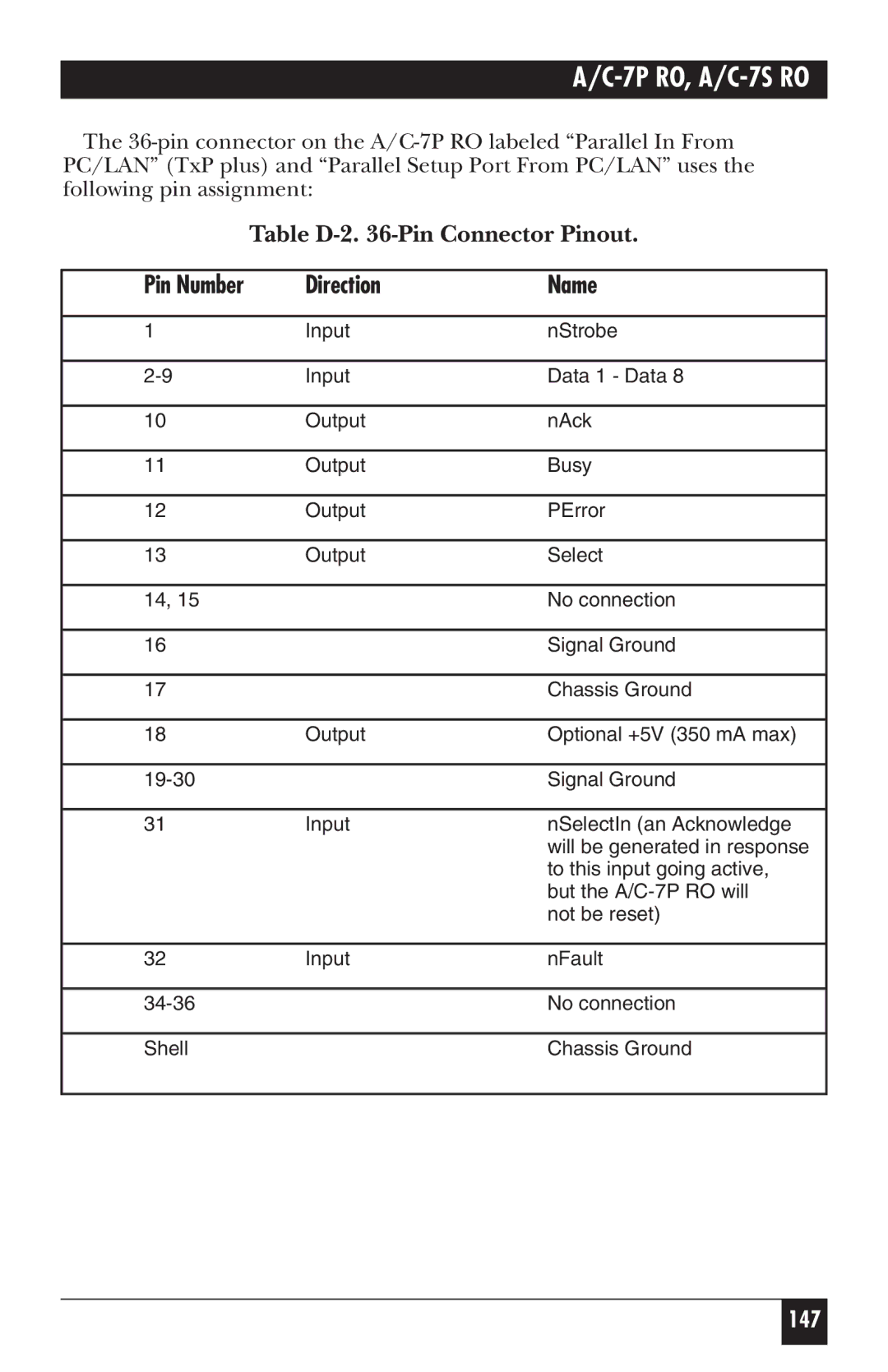
Appendix D Parallel-Port Specifications
Pin Number Direction Name
Table D-2 -Pin Connector Pinout
Appendix E Transferring Power To Pin
Figure E-1b
149
Copyright 2000. Black Box Corporation. All rights reserved