Manuals
/
Brands
/
Communications
/
Telephone
/
Bogen
/
Communications
/
Telephone
Bogen
LUMDMU
Connect the MDMU to the Telephone System
1
6
23
23
Download
23 pages, 231.31 Kb
Figure 2. Rack Mounted MDMU
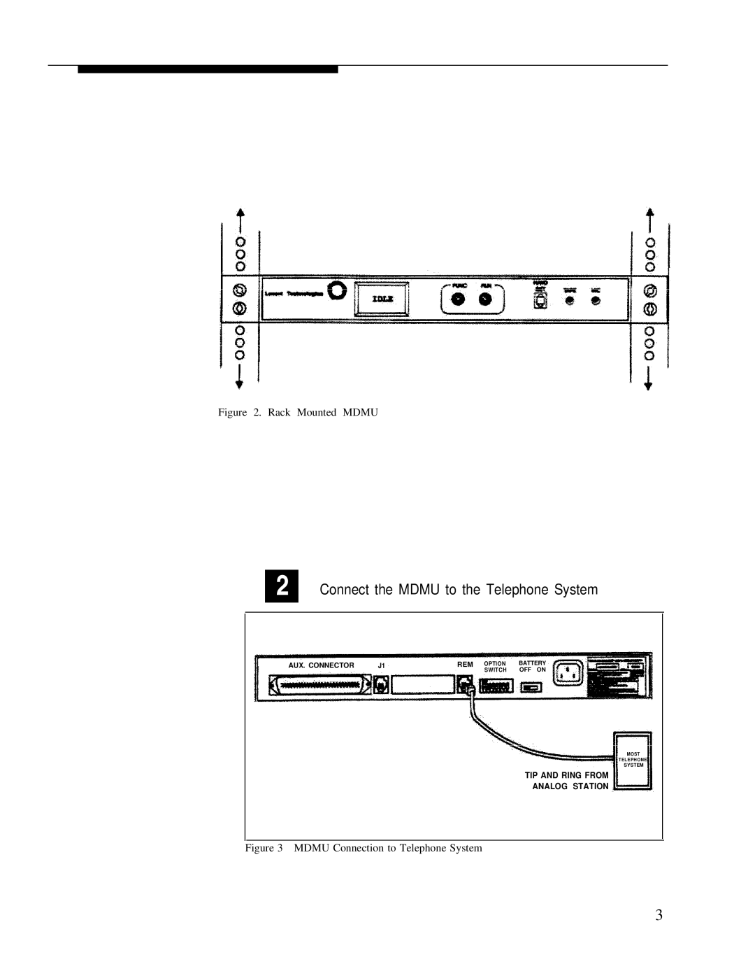
2
Connect the MDMU to the Telephone System
MOST
TELEPHONE
SYSTEM
AUX. CONNECTOR
J1
REM
OPTION
BATTERY
SWITCH
OFF ON
TIP AND RING FROM
ANALOG STATION
Figure 3 MDMU Connection to Telephone System
3
Contents
Main
Lucent Technologies
Multiple Digital Message Unit
Installation and Use Manual
Notice
FCC Statement (Part 15) - Radio Frequency Interference
Important Safety Information
Federal Communications Commission (FCC) Statement (Part 68)
Support Information
Table of Contents
iii
Introduction
Before You Start
Read important Safety Information on Page ii. Check Shipping Container Contents.
Have Required Tools
Installation Steps
Mount the MDMU to either a wall, cabinet or a rack (near the paging equipment if possible).
Figure 2. Rack Mounted MDMU
Connect the MDMU to the Telephone System
TIP AND RING FROM ANALOG STATION
Figure 3 MDMU Connection to Telephone System
Figure 4. MDMU Connection to Over Ride
Connect the RJ-21 cable/connector to the MDMU Aux. Interface and to terminal block.
Figure 5 Connection of RJ-21 Cable to MDMU.
Set the MDMU options on the DIP switch. Refer to the table below.
REM
OPTION BATTERY SWITCH OFF ON
Power Up System
Push the Battery slide switch to the ON position.
3.16
IDLE
The MDMU is now ready to record and play meassages.
Front Panel Operation
Controls and Indicators
Recording Messages
Page
Page
Playing Messages
Playing Messages in Sequence
Page
Page
Checking Message Times
Page
Page
Telephone Access Operation
Recording Messages
Listening to Recorded Messages
Playing Messages
Clearing a Message Sequence
Specifications