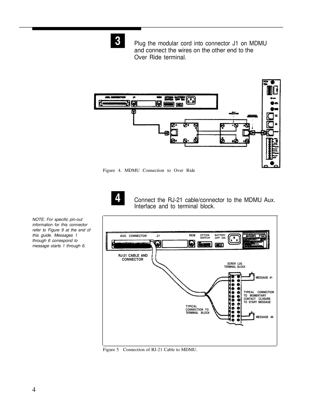
3 Plug the modular cord into connector J1 on MDMU and connect the wires on the other end to the Over Ride terminal.
NOTE: For specific
Figure 4. MDMU Connection to Over Ride
4 Connect the
AUX. CONNECTOR | J1 |
| REM OPTION | BATTERY |
|
|
| SWITCH | OFF ON |
|
|
RJ-21 CABLE AND
CONNECTOR
SCREW LUG
TERMINAL BLOCK
MESSAGE #1
TYPICAL CONNECTION
TO MOMENTARY
CONTACT CLOSURE
TO START MESSAGE
TYPICAL
CONNECTION TO
TERMINAL BLOCK
MESSAGE #6
Figure 5 Connection of RJ-21 Cable to MDMU.
4