Auxiliary Fence
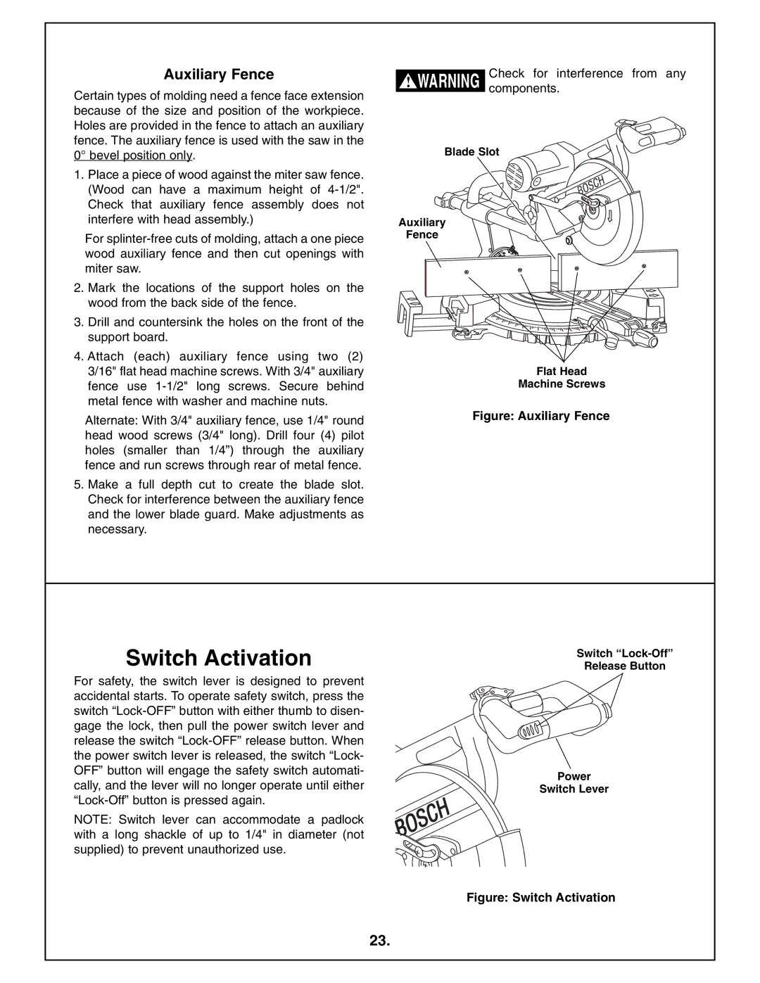
Certain types of molding need a fence face extension because of the size and position of the workpiece. Holes are provided in the fence to attach an auxiliary fence. The auxiliary fence is used with the saw in the 0° bevel position only.
1.Place a piece of wood against the miter saw fence. (Wood can have a maximum height of
For
2.Mark the locations of the support holes on the wood from the back side of the fence.
3.Drill and countersink the holes on the front of the support board.
4.Attach (each) auxiliary fence using two (2) 3/16" flat head machine screws. With 3/4" auxiliary fence use
Alternate: With 3/4" auxiliary fence, use 1/4" round head wood screws (3/4" long). Drill four (4) pilot holes (smaller than 1/4”) through the auxiliary fence and run screws through rear of metal fence.
5.Make a full depth cut to create the blade slot. Check for interference between the auxiliary fence and the lower blade guard. Make adjustments as necessary.
| Check for interference from any | |
! WARNING | ||
components. | ||
|
Blade Slot
Auxiliary
Fence
Flat Head
Machine Screws
Figure: Auxiliary Fence
Switch Activation
For safety, the switch lever is designed to prevent accidental starts. To operate safety switch, press the switch
NOTE: Switch lever can accommodate a padlock with a long shackle of up to 1/4" in diameter (not supplied) to prevent unauthorized use.
Switch “Lock-Off”
Release Button
Power
Switch Lever
Figure: Switch Activation
23.