Router Table Assembly
ASSEMBLING THE FENCE
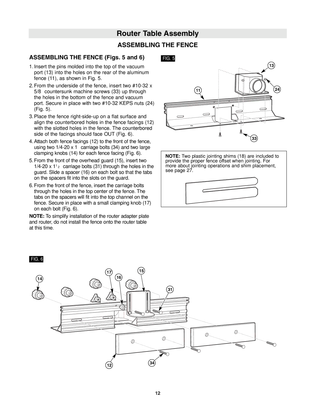
ASSEMBLING THE FENCE (Figs. 5 and 6)
1. Insert the pins molded into the top of the vacuum |
port (13) into the holes on the rear of the aluminum |
fence (11), as shown in Fig. 5. |
2. From the underside of the fence, insert two |
5/8″ countersunk machine screws (33) up through |
the holes in the bottom of the fence and vacuum |
port. Secure in place with two |
(Fig. 5). |
3. Place the fence |
align the counterbored holes in the fence facings (12) |
with the slotted holes in the fence. The counterbored |
side of the facings should face OUT (Fig. 6). |
4. Attach both fence facings (12) to the front of the fence, |
using two |
clamping knobs (14) for each fence facing (Fig. 6). |
FIG. 5
11
13
24
33
5. From the front of the overhead guard (15), insert two |
guard. Slide a spacer (16) on each bolt so that the tabs |
on the spacers fit into the slots on the guard. |
6. From the front of the fence, insert the carriage bolts |
through the holes in the top center of the fence. The |
tabs on the spacers will fit into the top channel on the |
fence. Secure in place with a small clamping knob (17) |
on each bolt (Fig. 6). |
NOTE: To simplify installation of the router adapter plate and router, do not install the fence onto the router table at this time.
NOTE: Two plastic jointing shims (18) are included to provide the proper fence offset when jointing. For more about jointing operations and shim placement, see page 27.
FIG. 6
1715
14 | 16 |
|
31
1234
12