Router Table Assembly
CHART 1
Router | Router | Hole | Fasteners | Mount |
Brand | Model | Pattern | Required | Type |
|
|
|
|
|
Bosch | 1613 series | A | 2 | |
|
|
| washers (27), and |
|
|
|
|
|
|
Bosch | 1617 series (fixed | B | 1 | |
| base models only) |
|
|
|
|
|
|
|
|
Bosch | 1619EVS | C | 2 | |
|
|
| washers (27), and |
|
|
|
|
|
|
Craftsman | Most Craftsman | E | 1 | |
| 1/2″ collet routers |
|
|
|
|
|
|
|
|
DeWalt | DW616, DW618 | B | 1 | |
| (fixed base only) |
|
|
|
|
|
|
|
|
Hitachi | M12VC | B | 1 | |
|
|
|
|
|
Makita | RF1100, RF1101 | B | 1 | |
|
|
|
|
|
Milwaukee | 5615, 5616 | B | 1 | |
|
|
|
|
|
Porter Cable | 690 series, | B | 1 | |
| 7529 plunge router, |
|
|
|
| and |
|
|
|
| (fixed base only) |
|
|
|
|
|
|
|
|
Ryobi | R161, R162 | E | 1 | |
|
|
|
|
|
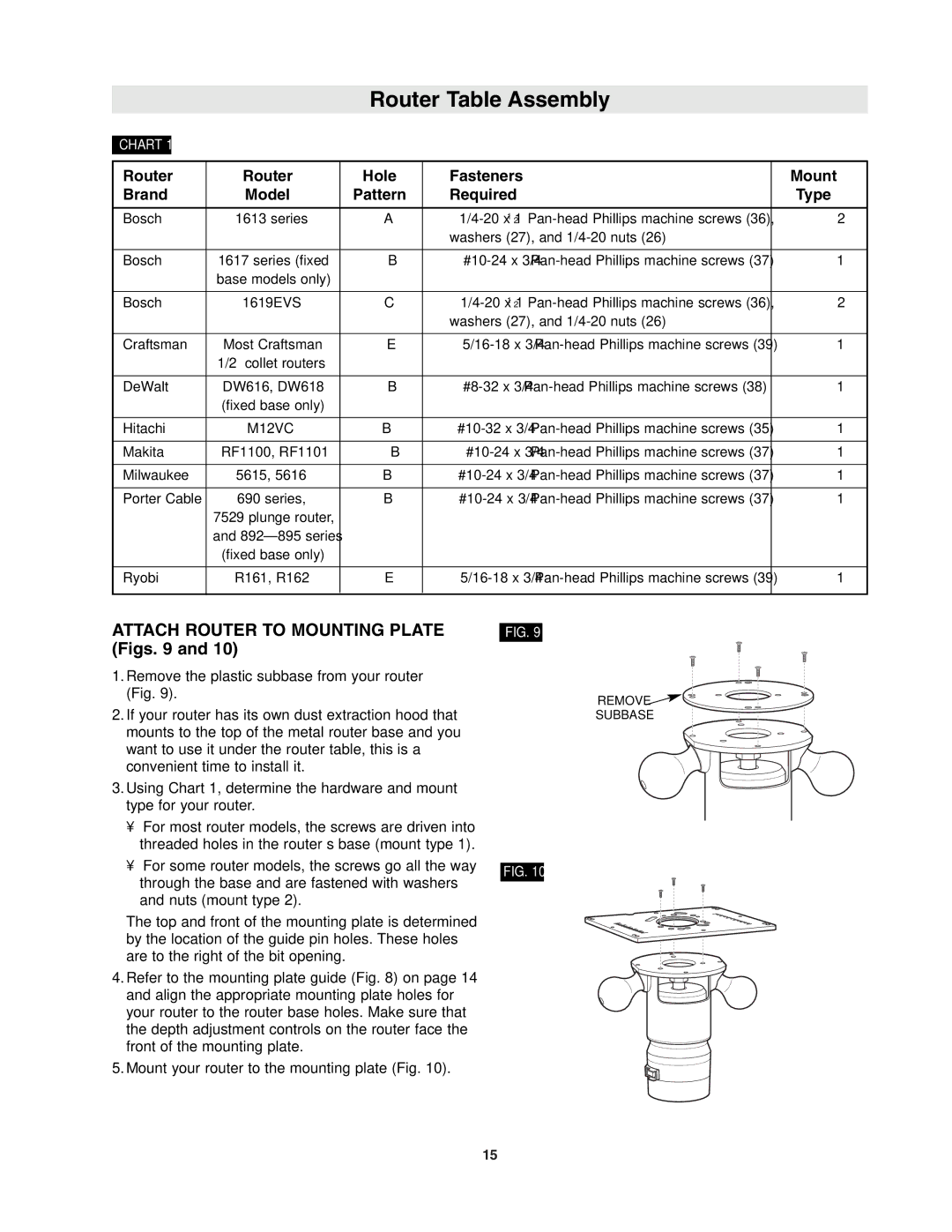
ATTACH ROUTER TO MOUNTING PLATE (Figs. 9 and 10)
1.Remove the plastic subbase from your router (Fig. 9).
2.If your router has its own dust extraction hood that mounts to the top of the metal router base and you want to use it under the router table, this is a convenient time to install it.
3.Using Chart 1, determine the hardware and mount type for your router.
•For most router models, the screws are driven into threaded holes in the router’s base (mount type 1).
•For some router models, the screws go all the way through the base and are fastened with washers and nuts (mount type 2).
The top and front of the mounting plate is determined by the location of the guide pin holes. These holes are to the right of the bit opening.
4.Refer to the mounting plate guide (Fig. 8) on page 14 and align the appropriate mounting plate holes for your router to the router base holes. Make sure that the depth adjustment controls on the router face the front of the mounting plate.
5.Mount your router to the mounting plate (Fig. 10).
FIG. 9
FIG. 10
REMOVE ![]() SUBBASE
SUBBASE
15