4
Interpreting LED Activity
Interpreting LED Activity
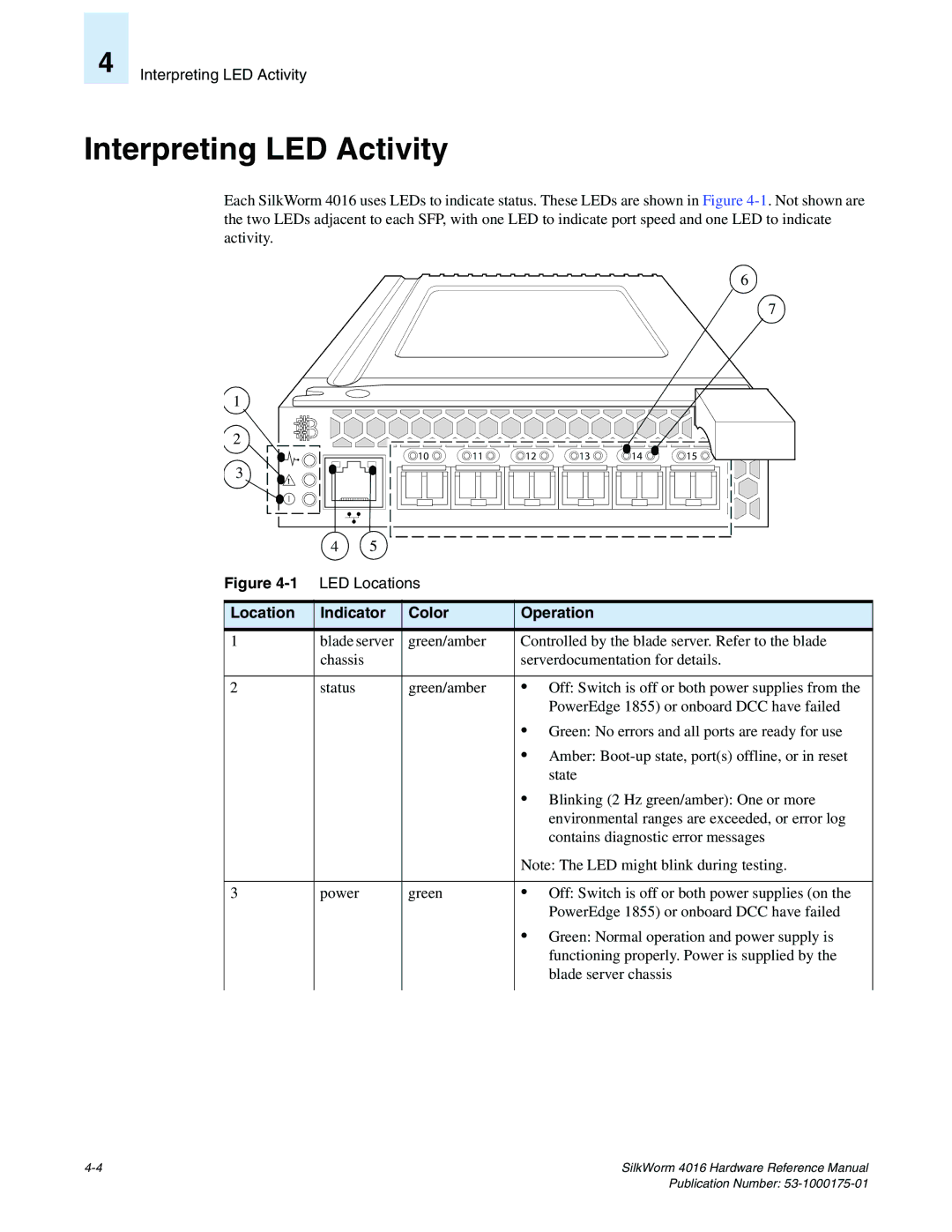
Each SilkWorm 4016 uses LEDs to indicate status. These LEDs are shown in Figure
1
2 |
3 |
! |
6
7
10 | 11 | 12 | 13 | 14 | 15 |
| 4 | 5 |
|
|
Figure |
| |||
|
|
|
| |
Location | Indicator | Color | Operation | |
|
|
|
| |
1 | blade server | green/amber | Controlled by the blade server. Refer to the blade | |
| chassis |
|
| serverdocumentation for details. |
|
|
|
|
|
2 | status |
| green/amber | • Off: Switch is off or both power supplies from the |
|
|
|
| PowerEdge 1855) or onboard DCC have failed |
|
|
|
| • Green: No errors and all ports are ready for use |
|
|
|
| • Amber: |
|
|
|
| state |
|
|
|
| • Blinking (2 Hz green/amber): One or more |
|
|
|
| environmental ranges are exceeded, or error log |
|
|
|
| contains diagnostic error messages |
|
|
|
| Note: The LED might blink during testing. |
|
|
|
|
|
3 | power |
| green | • Off: Switch is off or both power supplies (on the |
|
|
|
| PowerEdge 1855) or onboard DCC have failed |
|
|
|
| • Green: Normal operation and power supply is |
|
|
|
| functioning properly. Power is supplied by the |
|
|
|
| blade server chassis |
|
|
|
|
|
SilkWorm 4016 Hardware Reference Manual |