Inserting a SilkWorm 4016 into the Chassis
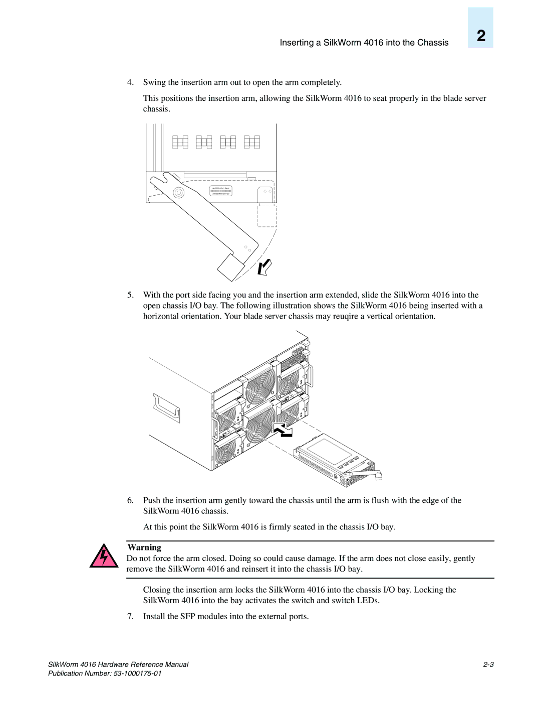
4.Swing the insertion arm out to open the arm completely.
2
This positions the insertion arm, allowing the SilkWorm 4016 to seat properly in the blade server chassis.
XXX 10:00:00:05:1E:34:70:29 |
5.With the port side facing you and the insertion arm extended, slide the SilkWorm 4016 into the open chassis I/O bay. The following illustration shows the SilkWorm 4016 being inserted with a horizontal orientation. Your blade server chassis may reuqire a vertical orientation.
NET2 NET4 PSU4
PSU2
I |
IOIO |
|
|
|
|
|
| minu | tes! |
|
|
|
|
| in 2 |
| |
|
|
|
| with |
|
|
|
|
|
| be re | placed |
|
|
|
|
| must |
|
|
|
| |
|
|
|
|
|
|
| |
FAN | module |
|
|
|
|
| |
|
|
|
|
|
|
| |
|
|
|
|
|
| minu | tes! |
|
|
|
|
| n 2 |
| |
|
|
|
| withi |
|
|
|
|
|
| be re | placed |
|
|
|
|
| ust |
|
|
|
| |
| modu | le m |
|
|
|
|
|
FAN |
|
|
|
|
|
| |
|
|
|
|
|
|
| |
OI
12 11
![]()
![]() NET1 13
NET1 13 ![]()
![]()
![]()
![]()
![]()
![]()
![]()
![]() NET3
NET3
PSU
1
A
scale: 1/8" = 1"
6.Push the insertion arm gently toward the chassis until the arm is flush with the edge of the SilkWorm 4016 chassis.
At this point the SilkWorm 4016 is firmly seated in the chassis I/O bay.
Warning
Do not force the arm closed. Doing so could cause damage. If the arm does not close easily, gently remove the SilkWorm 4016 and reinsert it into the chassis I/O bay.
Closing the insertion arm locks the SilkWorm 4016 into the chassis I/O bay. Locking the
SilkWorm 4016 into the bay activates the switch and switch LEDs.
7.Install the SFP modules into the external ports.
SilkWorm 4016 Hardware Reference Manual |