1
Switch Characteristics
Port Side
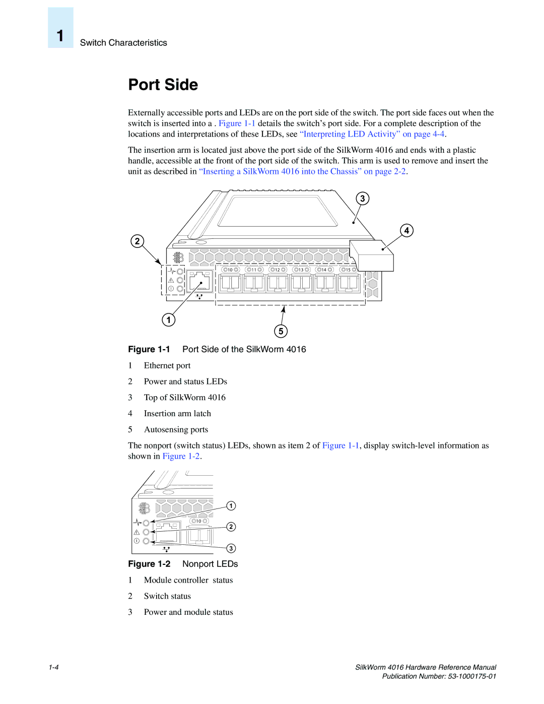
Externally accessible ports and LEDs are on the port side of the switch. The port side faces out when the switch is inserted into a . Figure
The insertion arm is located just above the port side of the SilkWorm 4016 and ends with a plastic handle, accessible at the front of the port side of the switch. This arm is used to remove and insert the unit as described in “Inserting a SilkWorm 4016 into the Chassis” on page
2
! |
3
4
10 | 11 | 12 | 13 | 14 | 15 |
1
5
Figure 1-1 Port Side of the SilkWorm 4016
1Ethernet port
2Power and status LEDs
3Top of SilkWorm 4016
4Insertion arm latch
5Autosensing ports
The nonport (switch status) LEDs, shown as item 2 of Figure
1 |
10 |
2 |
! |
3 |
Figure 1-2 Nonport LEDs
1Module controller status
2Switch status
3Power and module status
SilkWorm 4016 Hardware Reference Manual |