Removing and Replacing the SilkWorm 4016
4
6.Gently pull the handle of the SilkWorm 4016 insertion arm out and toward you to release the switch.
.
RP040000111
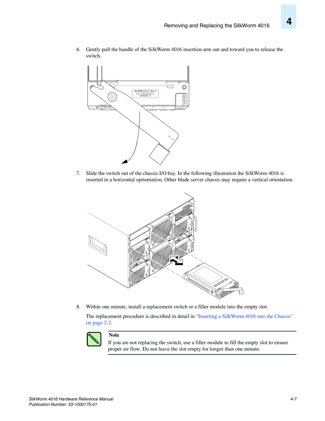
7.Slide the switch out of the chassis I/O bay. In the following illustration the SilkWorm 4016 is inserted in a horizontal oprientation. Other blade server chassis may require a vertical orientation.
NET2 NET4 PSU4
PSU2
I |
IOIO |
| mo | dule |
FAN |
|
|
| mod | ule |
FAN |
| |
|
|
must | be |
|
must | be |
|
|
|
|
|
| inut | es! |
|
|
| ithin | 2 m |
|
|
|
| d w |
|
|
| |
repl | ace |
|
|
|
|
|
| es! |
2 m | inut |
within
repla | ced |
|
12 11
I
13
![]()
![]() NET1 NET3 PSU
NET1 NET3 PSU
1
A
scale: 1/8" = 1"
8.Within one minute, install a replacement switch or a filler module into the empty slot.
The replacement procedure is described in detail in “Inserting a SilkWorm 4016 into the Chassis” on page
Note
If you are not replacing the switch, use a filler module to fill the empty slot to ensure proper air flow. Do not leave the slot empty for longer than one minute.
SilkWorm 4016 Hardware Reference Manual |