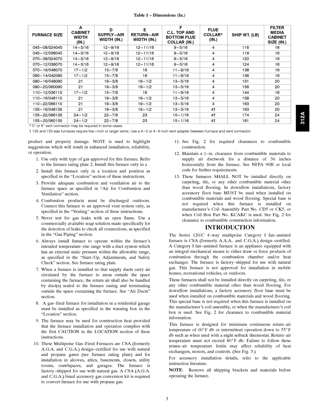
Table 1 – Dimensions (In.)


A


D


E


F

FLUE


FILTER


CABINET


C.L. TOP AND


MEDIA

FURNACE SIZE


SUPPLY AIR

RETURN AIR

COLLAR*

SHIP WT. (LB)

WIDTH


BOTTOM FLUE

CABINET


WIDTH (IN.)

WIDTH (IN.)


(IN.)


(IN.)


COLLAR (IN.)


SIZE (IN.)


045---

08/024045

14---

3/16


12---

9/16

12---

11/16


9---

5/16

4

116

16

045---

12/036045

14---

3/16


12---

9/16

12---

11/16


9---

5/16

4

119

16

070---

08/024070

14---

3/16


12---

9/16

12---

11/16


9---

5/16

4

120

16

070---

12/036070

14---

3/16


12---

9/16

12---

11/16


9---

5/16

4

124

16

070---

16/048070

17

--- 1/2


15---

7/8

16


11---

9/16

4

138

16

090---

14/042090

17

--- 1/2


15---

7/8

16


11---

9/16

4

136

16

090---

16/048090


21


19---

3/8

19---

1/2


13---

5/16

4

151

20

090---

20/060090


21


19---

3/8

19---

1/2


13---

5/16

4

156

20

110---

12/036110

17

--- 1/2


15---

7/8

16


11---

9/16

4

144

16

110---

16/048110


21


19---

3/8

19---

1/2


13---

5/16

4

158

20

110---

22/066110


21


19---

3/8

19---

1/2


13---

5/16

4

163

20

135---

16/048135


21


19---

3/8

19---

1/2


13---

5/16

4†

163

20

135---

22/066135

24

--- 1/2


22---

7/8

23


15---

1/16

4†

174

24

155---

20/060155

24

--- 1/2


22---

7/8

23


15---

1/16

4†

181

24

* 5” or 6” vent connector

may be required


in some cases.


{ 135 and 155 size furnaces require five

---

inch or larger vents. Use a 4---

5 or 4---

6 inch vent adapter between furnace and vent connector.


312A

product and property damage. NOTE is used to highlight suggestions which will result in enhanced installation, reliability, or operation.

1.Use only with type of gas approved for this furnace. Refer to the furnace rating plate 2. Install this furnace only in a

2.Install this furnace only in a location and position as specified in the “Location” section of these instructions.

3.Provide adequate combustion and ventilation air to the furnace space as specified in “Air for Combustion and Ventilation” section.

4.Combustion products must be discharged outdoors. Connect this furnace to an approved vent system only, as specified in the “Venting” section of these instructions.

5.Never test for gas leaks with an open flame. Use a commercially available soap solution made specifically for the detection of leaks to check all connections, as specified in the “Gas Piping” section.

6.Always install furnace to operate within the furnace’s intended temperature-rise range with a duct system which has an external static pressure within the allowable range, as specified in the “Start-Up, Adjustments, and Safety Check” section. See furnace rating plate.

7.When a furnace is installed so that supply ducts carry air circulated by the furnace to areas outside the space containing the furnace, the return air shall also be handled by duct(s) sealed to the furnace casing and terminating outside the space containing the furnace. See “Air Ducts” section.

8.A gas-fired furnace for installation in a residential garage must be installed as specified in the warning box in the “Location” section.

9.The furnace may be used for construction heat provided that the furnace installation and operation complies with the first CAUTION in the LOCATION section of these instructions.

10.These Multipoise Gas-Fired Furnaces are CSA (formerly A.G.A. and C.G.A.) design-certified for use with natural and propane gases (see furnace rating plate) and for installation in alcoves, attics, basements, closets, utility rooms, crawlspaces, and garages. The furnace is factory-shipped for use with natural gas. A CSA (A.G.A. and C.G.A.) listed accessory gas conversion kit is required to convert furnace for use with propane gas.

11.See Fig. 2 for required clearances to combustible construction.

12.Maintain a 1-in. clearance from combustible materials to supply air ductwork for a distance of 36 inches horizontally from the furnace. See NFPA 90B or local code for further requirements.

13.These furnaces SHALL NOT be installed directly on carpeting, tile, or any other combustible material other than wood flooring. In downflow installations, factory accessory floor base MUST be used when installed on combustible materials and wood flooring. Special base is not required when this furnace is installed on manufacturer’s Coil Assembly Part No. CD5 or CK5, or when Coil Box Part No. KCAKC is used. See Fig. 2 for clearance to combustible construction information.

INTRODUCTION

The Series 120/C 4-way multipoise Category I fan-assisted furnace is CSA (formerly A.A.A.. and C.G.A.) design-certified. A Category I fan-assisted furnace is an appliance equipped with an integral mechanical means to either draw or force products of combustion through the combustion chamber and/or heat exchanger. The furnace is factory-shipped for use with natural gas. This furnace is not approved for installation in mobile homes, recreational vehicles, or outdoors.

These furnaces shall not be installed directly on carpeting, tile, or any other combustible material other than wood flooring. For downflow installations, a factory accessory floor base must be used when installed on combustible materials and wood flooring. This special base is not required when this furnace is installed on the manufacturer’s coil assembly, or when the manufacturer’s coil box is used. See Fig. 2 for clearance to combustible material information.

This furnace is designed for minimum continuous return-air temperature of 60_F db or intermittent operation down to 55_F db such as when used with a night setback thermostat. Return-air temperature must not exceed 80_F db. Failure to follow these return-air temperature limits may affect reliability of heat exchangers, motors, and controls. (See Fig. 3.)

For accessory installation details, refer to the applicable instruction literature.

NOTE: Remove all shipping brackets and materials before operating the furnace.

3

Page 3
Image 3
Bryant 120 instruction manual Introduction, Dimensions, Width Bottom Flue Cabinet, Size

120 specifications

The Bryant 120 is a remarkable system designed for residential and commercial heating and cooling needs, showcasing an impressive blend of efficiency, reliability, and advanced technology. As a part of Bryant's extensive line of HVAC solutions, the Bryant 120 stands out with its features and performance, making it an ideal choice for those seeking comfort year-round.

One of the main features of the Bryant 120 is its exceptional energy efficiency. It boasts a high Seasonal Energy Efficiency Ratio (SEER) rating, enabling homeowners to save on energy costs while enjoying consistent temperature control. This efficiency is aided by its variable-speed compressor, which allows the system to adjust its output based on current requirements, optimizing both energy consumption and comfort.

In terms of technology, the Bryant 120 incorporates advanced controls that enhance user experience and system performance. The system comes equipped with smart thermostats that allow homeowners to monitor and adjust their environment remotely. These thermostats not only provide convenience but also help in optimizing energy usage by learning the household's heating and cooling patterns.

Another characteristic of the Bryant 120 is its durable construction. The unit is built to withstand various weather conditions, featuring a robust cabinet and components designed for longevity. This durability ensures that homeowners can rely on the system for years without the need for frequent repairs or replacements.

Noise levels are also a critical consideration in HVAC systems, and the Bryant 120 addresses this with its quiet operation. The system is designed to minimize sound output, making it suitable for residential areas where noise can be a concern. This is particularly beneficial for nighttime use, providing a comfortable sleeping environment.

Additionally, the Bryant 120 supports eco-friendly refrigerants that comply with environmental standards, contributing to a reduction in greenhouse gas emissions. This commitment to sustainability reflects Bryant's dedication to creating products that are not only effective but also responsible.

Overall, the Bryant 120 encapsulates a harmonious balance of efficiency, advanced technology, durability, and quiet operation. Whether for a new installation or a replacement, the Bryant 120 presents an ideal solution to meet diverse heating and cooling requirements, enhancing comfort while prioritizing energy savings and environmental responsibility.