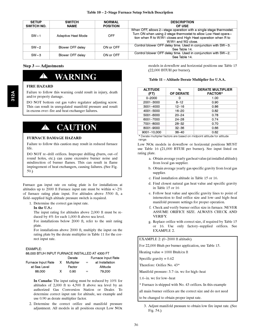
Table 10 – 2-Stage Furnace Setup Switch Description


SETUP

SWITCH

NORMAL

DESCRIPTION

SWITCH NO.

NAME

POSITION

OF USE


When OFF, allows 2--- stage operation with a single stage thermostat.

SW--- 1

Adaptive Heat Mode

OFF

Turn ON when using 2 stage thermostat to allow Low Heat opera---

tion when R to W/W1 closes and High Heat operation when R to


W/W1 and W2 close.

SW--- 2

Blower OFF delay

ON or OFF

Control blower OFF delay time. Used in conjunction with SW--- 3.

See Table 14.


SW--- 3

Blower OFF delay

ON or OFF

Control blower OFF delay time. Used in conjunction with SW--- 2.

See Table 14.


312A

Step 3 — Adjustments

!WARNING

FIRE HAZARD

Failure to follow this warning could result in injury, death and/or property damage.

DO NOT bottom out gas valve regulator adjusting screw. This can result in unregulated manifold pressure and result in excess over-fire and heat exchanger failures.

!CAUTION

FURNACE DAMAGE HAZARD

Failure to follow this caution may result in reduced furnace life.

DO NOT re-drill orifices. Improper drilling (burrs, out-of round holes, etc.) can cause excessive burner noise and misdirection of burner flames. This can result in flame impingement of heat exchangers, causing failures. (See Fig. 50.)

Furnace gas input rate on rating plate is for installations at altitudes up to 2000 ft Furnace input rate must be within +/-2% of furnace rating plate input. For altitudes above 5500 ft, a field-supplied high altitude pressure switch is required.

1.Determine the correct gas input rate.

In the U.S.:

The input rating for altitudes above 2,000 ft must be re- duced by 4% for each 1,000 ft above sea level.

For installations below 2000 ft, refer to the unit rating plate.

For installations above 2000 ft, multiply the input on the rating plate by the derate multiplier in Table 11 for the cor- rect input rate.

EXAMPLE:

88,000 BTUH INPUT FURNACE INSTALLED AT 4300 FT


Derate


Furnace Input Rate

Furnace Input Rate

X

Multiplier

=

at Installation

at Sea Level


Factor


Altitude

88,000

X

0.90

=

79,200

In Canada: The input rating must be reduced by 10% for altitudes of 2,000 ft to 4,500 ft above sea level by an authorized Gas Conversion Station or Dealer. To determine correct input rate for altitude, see example and use 0.90 as derate multiplier factor.

2.Determine the correct orifice and manifold pressure adjustment. All models in all positions except Low NOx

models in downflow and horizontal positions use Table 15 (22,000 BTUH per burner).

Table 11 – Altitude Derate Multiplier for U.S.A.

ALTITUDE

%

DERATE MULTIPLIER

(FT)

OF DERATE

FACTOR*

0–2000

0

1.00

2001–3000

8–12

0.90

3001–4000

12–16

0.86

4001–5000

16–20

0.82

5001–6000

20–24

0.78

6001–7000

24–28

0.74

7001–8000

28–32

0.70

8001–9000

32–36

0.66

9001–10,000

36–40

0.62

*Derate multiplier factors are based on midpoint altitude for altitude range.

Low NOx models in downflow or horizontal positions MUST use Table 16 (21,000 BTUH per burner). See input listed on rating plate.

a.Obtain average yearly gas heat value (at installed altitude) from local gas supplier.

b.Obtain average yearly gas specific gravity from local gas supplier.

c.Find installation altitude in Table 15 or 16.

d.Find closest natural gas heat value and specific gravity in Table 15 or 16

e.Follow heat value and specific gravity lines to point of intersection to find orifice size and low-and high-heat manifold pressure settings for proper operation.

f.Check and verify burner orifice size in furnace. NEVER ASSUME ORIFICE SIZE. ALWAYS CHECK AND VERIFY.

g.Replace orifice with correct size, if required by Table 15 or 16. Use only factory-supplied orifices. See EXAMPLE 2.

EXAMPLE 2: (0-2000 ft altitude)

For 22,000 Btuh per burner application, use Table 15. Heating value = 1000 Btuh/cu ft

Specific gravity = 0.62 Therefore: Orifice No. 43*

Manifold pressure: 3.7-in. wc for high-heat 1.6-in. wc for low-heat

*Furnace is shipped with No. 43 orifices. In this example all main burner orifices are the correct size and do not need to be changed to obtain proper input rate.

3.Adjust manifold pressure to obtain low fire input rate. (See Fig. 54.)

36

Page 36
Image 36
Bryant 120 instruction manual Adjustments, Stage Furnace Setup Switch Description, Altitude Derate Multiplier for U.S.A

120 specifications

The Bryant 120 is a remarkable system designed for residential and commercial heating and cooling needs, showcasing an impressive blend of efficiency, reliability, and advanced technology. As a part of Bryant's extensive line of HVAC solutions, the Bryant 120 stands out with its features and performance, making it an ideal choice for those seeking comfort year-round.

One of the main features of the Bryant 120 is its exceptional energy efficiency. It boasts a high Seasonal Energy Efficiency Ratio (SEER) rating, enabling homeowners to save on energy costs while enjoying consistent temperature control. This efficiency is aided by its variable-speed compressor, which allows the system to adjust its output based on current requirements, optimizing both energy consumption and comfort.

In terms of technology, the Bryant 120 incorporates advanced controls that enhance user experience and system performance. The system comes equipped with smart thermostats that allow homeowners to monitor and adjust their environment remotely. These thermostats not only provide convenience but also help in optimizing energy usage by learning the household's heating and cooling patterns.

Another characteristic of the Bryant 120 is its durable construction. The unit is built to withstand various weather conditions, featuring a robust cabinet and components designed for longevity. This durability ensures that homeowners can rely on the system for years without the need for frequent repairs or replacements.

Noise levels are also a critical consideration in HVAC systems, and the Bryant 120 addresses this with its quiet operation. The system is designed to minimize sound output, making it suitable for residential areas where noise can be a concern. This is particularly beneficial for nighttime use, providing a comfortable sleeping environment.

Additionally, the Bryant 120 supports eco-friendly refrigerants that comply with environmental standards, contributing to a reduction in greenhouse gas emissions. This commitment to sustainability reflects Bryant's dedication to creating products that are not only effective but also responsible.

Overall, the Bryant 120 encapsulates a harmonious balance of efficiency, advanced technology, durability, and quiet operation. Whether for a new installation or a replacement, the Bryant 120 presents an ideal solution to meet diverse heating and cooling requirements, enhancing comfort while prioritizing energy savings and environmental responsibility.