Part Number 04-0053-01 Rev. a Order Number
SmartSwitch ATM Switch User Guide
Ii SmartSwitch ATM Switch User Guide
FCC Class a Notice
Product Name
Application of Council Directives
Manufacturer’s Name
Manufacturer’s Address
Safety Information Class 1 Laser Transceivers
Fiber Optic Protective Caps
Regulatory Compliance Summary Safety
Document Name
Revision History
Table of Contents
Virtual Ports and Static Connections
Index
Table of Contents Xii SmartSwitch ATM User Guide
List of Figures
List of Figures Xiv SmartSwitch ATM User Guide
List of Tables
List of Tables Xvi SmartSwitch ATM User Guide
Introduction
Contents of the User Guide
Smartswitch ATM Switch Differences
Subnet mask is for example only
IP Over ATM and Lane
Creating AN IP Over ATM Vlan
IP address is for example only
Creating an IP over ATM Vlan IP Over ATM and Lane
Default IP Over ATM Local Client Address
Default ATM Addressing for IP over ATM
Default Netprefix for SmartSwitch 2500 Family Switches
Default Netprefix for SmartSwitch
Creating AN Emulated LAN
Ilmi
ATM Addressing for LAN Emulation
SmartSwitch 2500 Family Default Lane Addressing
CPU MAC address = 0020D4144180 Elan number = Then
SmartSwitch 6500 Default Lane Addressing
Lecs address is constructed from
Chassis MAC address = 0020D4144180 Then
Chassis MAC address = 00001DA3870B Elan number = Then
ELANs Across Multiple Switches
Chassis MAC address = 00001DA3870B Then
Just for this example
Switch Clients
Distributed Lane Services
Specify the LES address on SW2
Use the add leselan command to create an LES on switch SW2
SW1 # show client
Elan Join Policies
Best Effort Elan Join Test
By Route Descriptor
By MAC Address
Use ? to see possible types
Weight the policy at
Lecselanlec Table
Elan is specified by Elan number
Lane Over WAN Circuits
Physical Versus Logical BUS Multicasting
No MAC address is specified
Single PVP connection between clients and Lane services
Lane Service Redundancy
Using Lnni
Lnni Redundant LECSs on same network
Lane Load Sharing
Lnni call set up load sharing
How Lnni handles Elan join requests
Setting up Lnni LECs
SW2# set lnniinfo
SW1 # stop lecs
SW1 # stop les
SW1 # set lnniinfo
SW2 # add elan
On SW1, create an Elan in this example, we create elan1
Similarly, create the same Elan elan1 on SW2
SW1 # add elan
SW1 # show lecsneighborinfo
Configuring Lnni Distributed LES/BUS Servers
SW2 # show elan
On switch SW3, use the set lnniinfo to configure Lnni
SW3 # start les
LES
SW1 # show lecsserverlist
Page
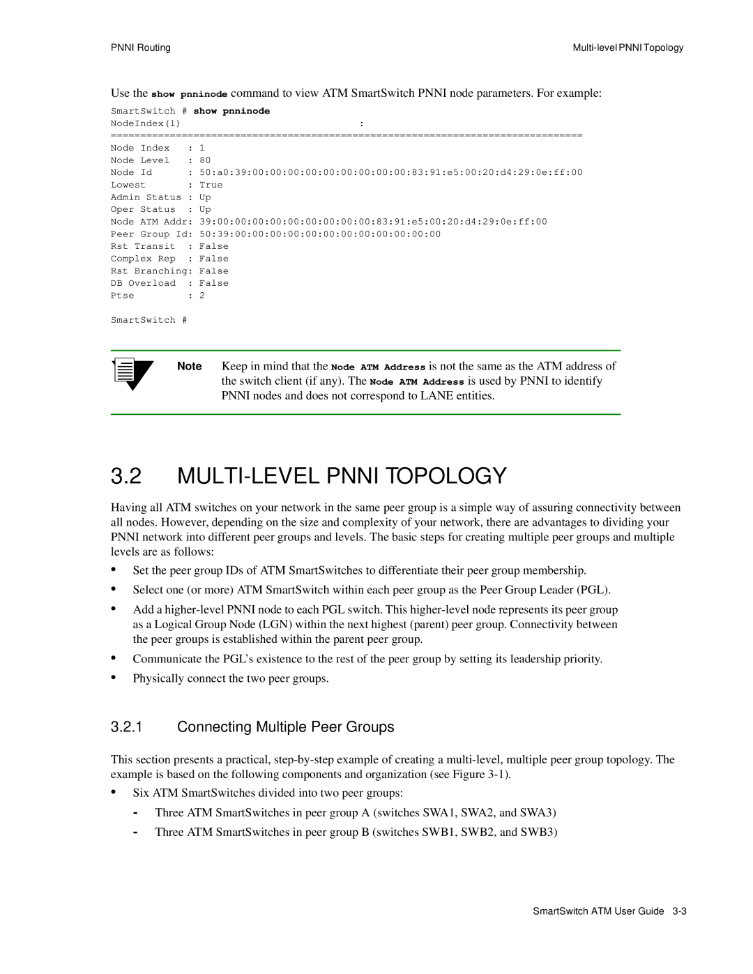
Pnni Routing
Default Pnni Addressing
SmartSwitch 2500 Family Default Node ID
SmartSwitch 6500 Family Default Node ID
SmartSwitch 6500 Default Node ATM Address
SmartSwitch 2500 Family Default Node ATM Address
MULTI-LEVEL Pnni Topology
Connecting Multiple Peer Groups
Change the tenth byte to
SWA1 # set pnnipeergroupid
Highest priority in election process
Do the same for switch SWB3
Specifies node number
SWA3 # show pnnipglelection
Do the same on switch SWB3
SWB3 # set pnnipglelection
Adding Higher-level Peer Groups
Physical Connections Between Peer Groups
Adding a third Pnni node for next level connectivity
Managing Parallel Pnni Links
SmartSwitch # show pnniinterface
Aggregation Tokens
Perform the same operation on switch SWB2 in group B
7b2 Link on switch SWA2 comes from this port
4a3 Link on switch SWB2 comes from this port
Aggregation token values and parallel links
Pnni Link Timing
SmartSwitch # set linkmonitortimeout
This is an exterior route
Routing
Additional Routing Protocols
Iisp Routes
Iisp Routing Considerations
Iisp Routing Example Two
Iisp Routing Example One
Iisp Link Timing
Set linkmonitortimeout
Advertise this address into the Pnni domain
Take the default to make this an internal route
UNI Routes
Yes
UNI Link Timing
Creating Route Metrics
Administrative Weights
Route Metrics
Enter show pnnimetric to view the newly created metric pair
Create the outgoing member of the metric pair
Create the incoming member of the metric pair
90.1.1.254
IP Routing for Management
6b2
Index tag of our metric pair
Route NET Table
To see the route, enter the show route command on SW2
Point-to-Point PVCs
SmartSwitch # add trafficdescriptor
Virtual Ports and Static Connections
PVC Connections
Specify its VCI
Point-to-Multipoint PVCs
Specify first port
Specify its Vpci
Set PCRCLP01 to zero
Take the default values
Perform for ports 7a3 and 7a4
Set client number
Connecting to Local Switch Client Through a PVC
Connect the end node to port 7a1 of the ATM SmartSwitch
Use add ipatmclient to create an IP over ATM local client
Turn off Ilmi
Turn off signaling
PVP Connections
Specify the first port
Use the show pvp command to display the PVP connection
7b1
See note below
7a1.3, 5b2.3, A1.3, C5.3, and so on
Connecting PVPs
Virtual Ports
Available VPIs = 2MaxVpiBits
Creating Virtual Ports
Set to 1 this translates to VPIs = 2 1-1 =
Default MaxVpiBits =
Default MaxVciBits =
Instance of set portconfig
Specify virtual port number and Base VPI
.1 means our Base VPI is one
VPIs used = Base VPI + 2 0 1 = 1 + 0 =
MaxVciBits decrements by
Soft PVC and Soft PVP differences
Things To Watch Out For When Creating Virtual Ports
Soft PVC and PVP Connections
Creating a soft PVC
Making Soft PVC and PVP Connections
SmartSwitch # show spvcaddress
SmartSwitch # add spvcaddress
6b3 Port on target switch
102
7a1 Port on source switch
Creating a Soft PVP
We use VPI=
SmartSwitch # show spvp PortNumberALL
Soft PVC and PVP Connections
Traffic Descriptors
Traffic Management
Traffic Management Capabilities
PeakCellRate CLP0+1, PeakCellRate CLP0, Tag CLP =
No Traffic Descriptor
PeakCellRate CLP0+1
PeakCellRate CLP0+1, PeakCellRate CLP0
Call Admission Control Policy
Ubr
SmartSwitch # set caceqbwallocscheme
SmartSwitch # set cacserviceclassbw
CPU UBR
Queue Buffers
MinIndex for
7a3
Corresponds to CBR
EFCI, EPD, and RM Cell Marking
SmartSwitch # show switchtrafficcongestion
SmartSwitch # set switchtrafficcongestion
Traffic Management Capabilities
IP address of Tftp server
Firmware Upgrades and Bootline Commands
Update Firmware Commands
Unsuccessful Update
=df s
Bootline Commands
Enter the go command to start the ATM SmartSwitch
Accessing the Bootline Prompt
Bootline Commands Explanations
Swms
Changes the slave TSM/CPU to the master
Scsm
=df b
Upgrading Boot Load firmware
=df p
Upgrading Post Diagnostic firmware
Changing the Default Boot Load Image
=chpi
Bootline CommandsFirmware Upgrades and Bootline Commands
Upgrading Switch Operating firmware
Start the ATM SmartSwitch by entering the go command
Bootline Commands
How ATM Address Filters Work
ATM Filtering and Clocking
Port ATM Address Filters
Creating ATM Address Filters
Source and Destination Address Masks
ATM Address Filter Example
FFFFFFFFFFFFFFFFFFFF00000000000000000000
Port Clock Configuration
Filter Considerations Regarding Lane and IP over ATM
Network Clocking
Troubleshooting IP Over ATM
Troubleshooting
Troubleshooting LAN Emulation
Switches in Different Peer Groups
Troubleshooting Pnni Links
Switches in Same Peer Group
Fewer than 100 connections on a port Min = 64, Max =
Troubleshooting Congestion
Diagnosing Congestion
Global Congestion
Port Congestion
Event Categories
Events and Alarms
SmartSwitch # set eventdisplay
Viewing Events and Alarms
SmartSwitch # set alarmdisplay
Deleting Events and Alarms
IP address of my Tftp server
Login name on the server
Password
Saving Core Dumps
Saving Core Dumps
MIB, SMI, MIB Files and Internet MIB Hierarchy
Appendix a Agent Support
MIB, SMI, MIB Files and Internet MIB Hierarchy
CSI ZeitNet Proprietary MIBs
Relation Between Object Identifier and the Represented Value
CSI ZeitNet Proprietary MIB Groups
Supported protocols
Supported SMI Formats
Ctron
Non-Conformance
ATM SmartSwitch MIB Support
MIB Exceptions
Not Supported
Managing AN ATM Smartswitch
Console Commands that Affect the Agent
Update firmware Backup Restore Reboot
Default Community Strings
Telephone Assistance
FAX Service
Electronic Services
Appendix B Technical Support
Repair Services
Hardware Warranty
Software Warranty
Index
Accessing the boot load prompt
12,4-4,4-6
Iisp routing considerations
Fail-over timing Route type parameter
Multi-level Pnni topology
ZnSwitchDiscoveryTable
ZnPortTrafficCongTable
PNN
Enabling RM cell marking
Changing EPD thresholds
Vlan