ATM Routing | Switch Administration |
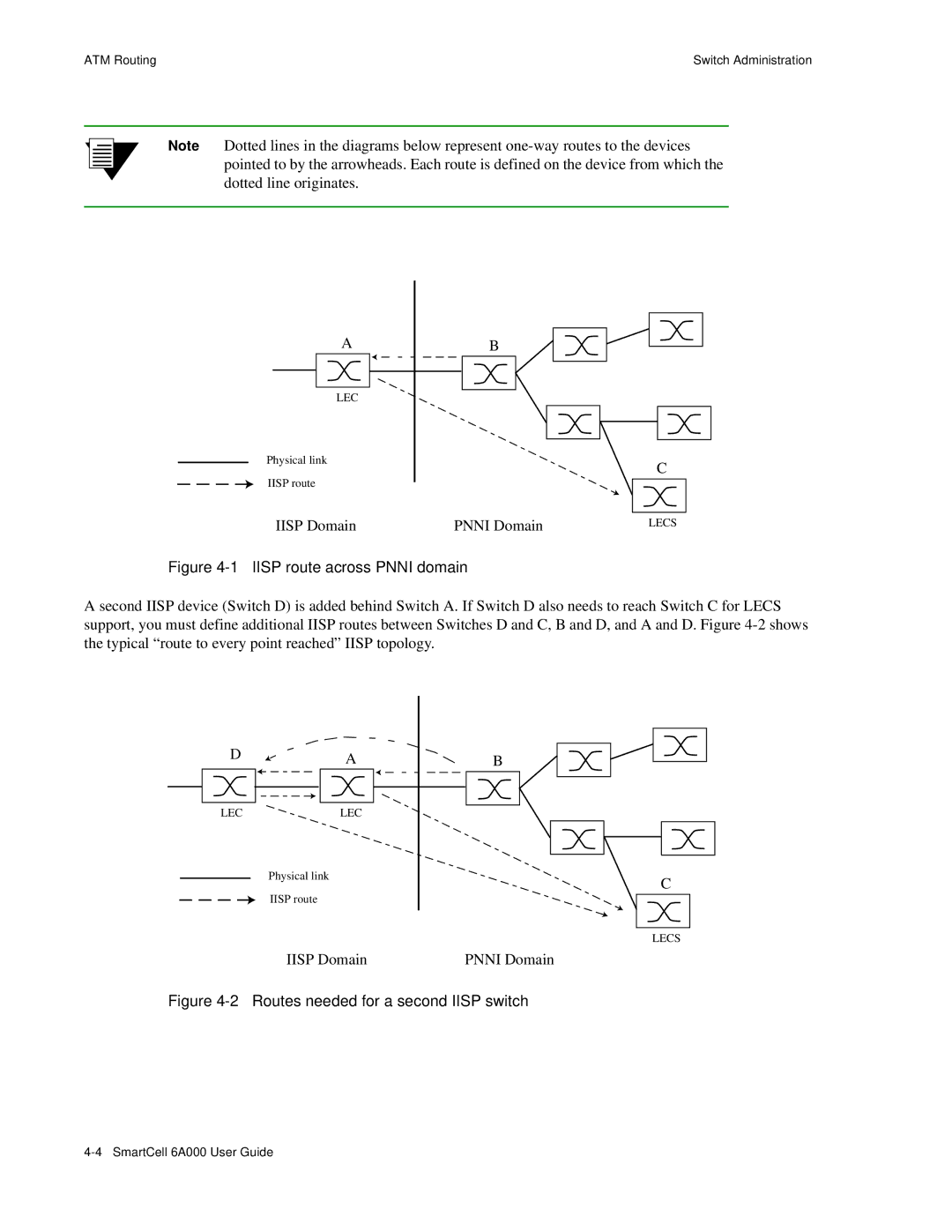
Note Dotted lines in the diagrams below represent
A
LEC
Physical link
IISP route
IISP Domain
B
C
PNNI Domain | LECS |
Figure 4-1 IISP route across PNNI domain
A second IISP device (Switch D) is added behind Switch A. If Switch D also needs to reach Switch C for LECS support, you must define additional IISP routes between Switches D and C, B and D, and A and D. Figure
D | A | B |
| ||
LEC | LEC |
|
| Physical link | C |
|
| |
| IISP route |
|
|
| LECS |
IISP Domain | PNNI Domain |