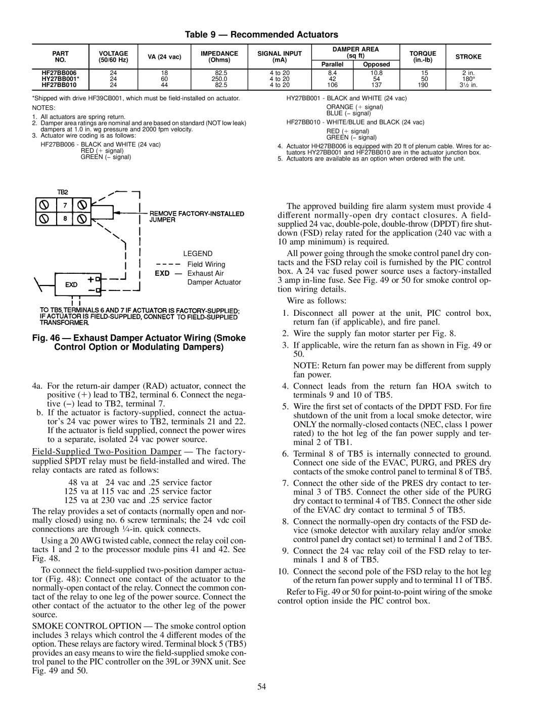
Table 9 Ð Recommended Actuators

PART

VOLTAGE


IMPEDANCE

SIGNAL INPUT

DAMPER AREA

TORQUE


VA (24 vac)


(sq ft)

STROKE

NO.

(50/60 Hz)

(Ohms)

(mA)


(in.-lb)


Parallel


Opposed


HF27BB006

24

18

82.5

4 to 20

8.4


10.8

15

2 in.

HY27BB001*

24

60

250.0

4 to 20

42


54

50

180°

HF27BB010

24

44

82.5

4 to 20

106


137

190

31¤2 in.

*Shipped with drive HF39CB001, which must be ®eld-installed on actuator.

NOTES:

1.All actuators are spring return.

2.Damper area ratings are nominal and are based on standard (NOT low leak) dampers at 1.0 in. wg pressure and 2000 fpm velocity.

3.Actuator wire coding is as follows:

HF27BB006 - BLACK and WHITE (24 vac) RED (1 signal)

GREEN (− signal)

HY27BB001 - BLACK and WHITE (24 vac)

ORANGE (1 signal)

BLUE (− signal)

HF27BB010 - WHITE/BLUE and BLACK (24 vac)

RED (1 signal)

GREEN (− signal)

4.Actuator HH27BB006 is equipped with 20 ft of plenum cable. Wires for ac- tuators HY27BB001 and HF27BB010 are in the actuator junction box.

5.Actuators are available as an option when ordered with the unit.

LEGEND

Field Wiring

EXD Ð Exhaust Air

Damper Actuator

Fig. 46 Ð Exhaust Damper Actuator Wiring (Smoke

Control Option or Modulating Dampers)

4a. For the return-air damper (RAD) actuator, connect the positive (1) lead to TB2, terminal 6. Connect the nega- tive (−) lead to TB2, terminal 7.

b.If the actuator is factory-supplied, connect the actua- tor's 24 vac power wires to TB2, terminals 21 and 22. If the actuator is ®eld supplied, connect the power wires to a separate, isolated 24 vac power source.

Field-SuppliedTwo-Position Damper Ð The factory- supplied SPDT relay must be ®eld-installed and wired. The relay contacts are rated as follows:

48 va at 24 vac and .25 service factor

125 va at 115 vac and .25 service factor

125 va at 230 vac and .25 service factor

The relay provides a set of contacts (normally open and nor- mally closed) using no. 6 screw terminals; the 24 vdc coil connections are through 1¤4-in. quick connects.

Using a 20 AWG twisted cable, connect the relay coil con- tacts 1 and 2 to the processor module pins 41 and 42. See Fig. 48.

To connect the ®eld-supplied two-position damper actua- tor (Fig. 48): Connect one contact of the actuator to the normally-open contact of the relay. Connect the common con- tact of the relay to one leg of the power source. Connect the other contact of the actuator to the other leg of the power source.

SMOKE CONTROL OPTION Ð The smoke control option includes 3 relays which control the 4 different modes of the option. These relays are factory wired. Terminal block 5 (TB5) provides an easy means to wire the ®eld-supplied smoke con- trol panel to the PIC controller on the 39L or 39NX unit. See Fig. 49 and 50.

The approved building ®re alarm system must provide 4 different normally-open dry contact closures. A ®eld- supplied 24 vac, double-pole, double-throw (DPDT) ®re shut- down (FSD) relay rated for the application (240 vac with a 10 amp minimum) is required.

All power going through the smoke control panel dry con- tacts and the FSD relay coil is furnished by the PIC control box. A 24 vac fused power source uses a factory-installed 3 amp in-line fuse. See Fig. 49 or 50 for smoke control op- tion wiring details.

Wire as follows:

1.Disconnect all power at the unit, PIC control box, return fan (if applicable), and ®re panel.

2.Wire the supply fan motor starter per Fig. 8.

3.If applicable, wire the return fan as shown in Fig. 49 or 50.

NOTE: Return fan power may be different from supply fan power.

4.Connect leads from the return fan HOA switch to terminals 9 and 10 of TB5.

5.Wire the ®rst set of contacts of the DPDT FSD. For ®re shutdown of the unit from a local smoke detector, wire ONLY the normally-closed contacts (NEC, class 1 power rated) to the hot leg of the fan power supply and ter- minal 2 of TB1.

6.Terminal 8 of TB5 is internally connected to ground. Connect one side of the EVAC, PURG, and PRES dry contacts of the smoke control panel to terminal 8 of TB5.

7.Connect the other side of the PRES dry contact to ter- minal 3 of TB5. Connect the other side of the PURG dry contact to terminal 4 of TB5. Connect the other side of the EVAC dry contact to terminal 5 of TB5.

8.Connect the normally-open dry contacts of the FSD de- vice (smoke detector with auxilary relay and/or smoke control panel dry contact set) to terminal 1 and 2 of TB5.

9.Connect the 24 vac relay coil of the FSD relay to ter- minals 1 and 8 of TB5.

10.Connect the second pole of the FSD relay to the hot leg of the return fan power supply and to terminal 11 of TB5.

Refer to Fig. 49 or 50 for point-to-point wiring of the smoke control option inside the PIC control box.

54

Page 54
Image 54
Carrier 39L specifications Recommended Actuators, Stroke

39L specifications

The Carrier 39L is a cutting-edge air conditioning unit designed for both residential and commercial applications, providing exceptional cooling and heating performance. Equipped with advanced technologies, this system ensures optimal climate control while maintaining energy efficiency.

One of the standout features of the Carrier 39L is its inverter technology. This innovation allows the system to adjust its compressor speed based on the ambient temperature, which results in a significant reduction in energy consumption. By operating at varying capacities rather than a fixed output, the 39L can maintain a consistent temperature, enhancing comfort while lowering electricity bills.

The Carrier 39L also includes a high-efficiency air filtration system, designed to capture dust, allergens, and other airborne particles. This not only improves indoor air quality but also promotes a healthier living environment. The filtration system is complemented by anti-bacterial treatment, ensuring that the air circulated within your space is both clean and refreshing.

In terms of design, the Carrier 39L boasts a sleek and compact form factor, making it easy to integrate into various settings, from homes to offices. Its quiet operation is another notable feature, as it minimizes noise levels, allowing occupants to enjoy a serene atmosphere without disruptive sound.

Further enhancing convenience, the Carrier 39L comes equipped with smart connectivity options. Users can control the unit remotely via a smartphone app, making it easy to adjust settings, program schedules, and monitor energy usage from anywhere. This feature not only improves user experience but also supports energy-saving practices.

Durability is also a key characteristic of the Carrier 39L. Constructed with high-quality materials and coated with corrosion-resistant treatments, the unit is built to withstand various environmental conditions. This ensures long-lasting performance and reduces the need for frequent maintenance.

Overall, the Carrier 39L is a versatile, efficient, and user-friendly air conditioning solution. Its blend of advanced technologies, energy-saving capabilities, and robust design makes it an ideal choice for those seeking reliable climate control in their spaces. Whether for residential comfort or commercial necessity, the Carrier 39L stands out as a leader in modern air conditioning.