Filter Status Switch Ð The ®lter status switch (FLTS) is factory-installed in the ®lter section on all PIC-equipped units. The switch is a snap-acting SPDT switch. When dirty ®lter elements cause the pressure drop across the ®lter me- dia to exceed the switch setting, the switch closes and sends an alarm signal to the PIC.

The 39L units use a single switch. In 39NX units, up to 3 switches can be connected in parallel. When the switches are wired in parallel, it is not possible to isolate an alarm signal to a single switch.

The FLTS has an operating range of 0.05 to 2.0 in. wg. Factory settings for the switch are as follows:

Filter Type

Setting (in. wg)

Flat

0.5

Bag/Cartridge

1.0

Final

1.5

The FLTS electrical ratings are as follows:

300 va pilot duty at 115 to 277 vac

10 amps non-inductive to 277 vac

Rated for NO (normally open) and NC (normally closed) contacts.

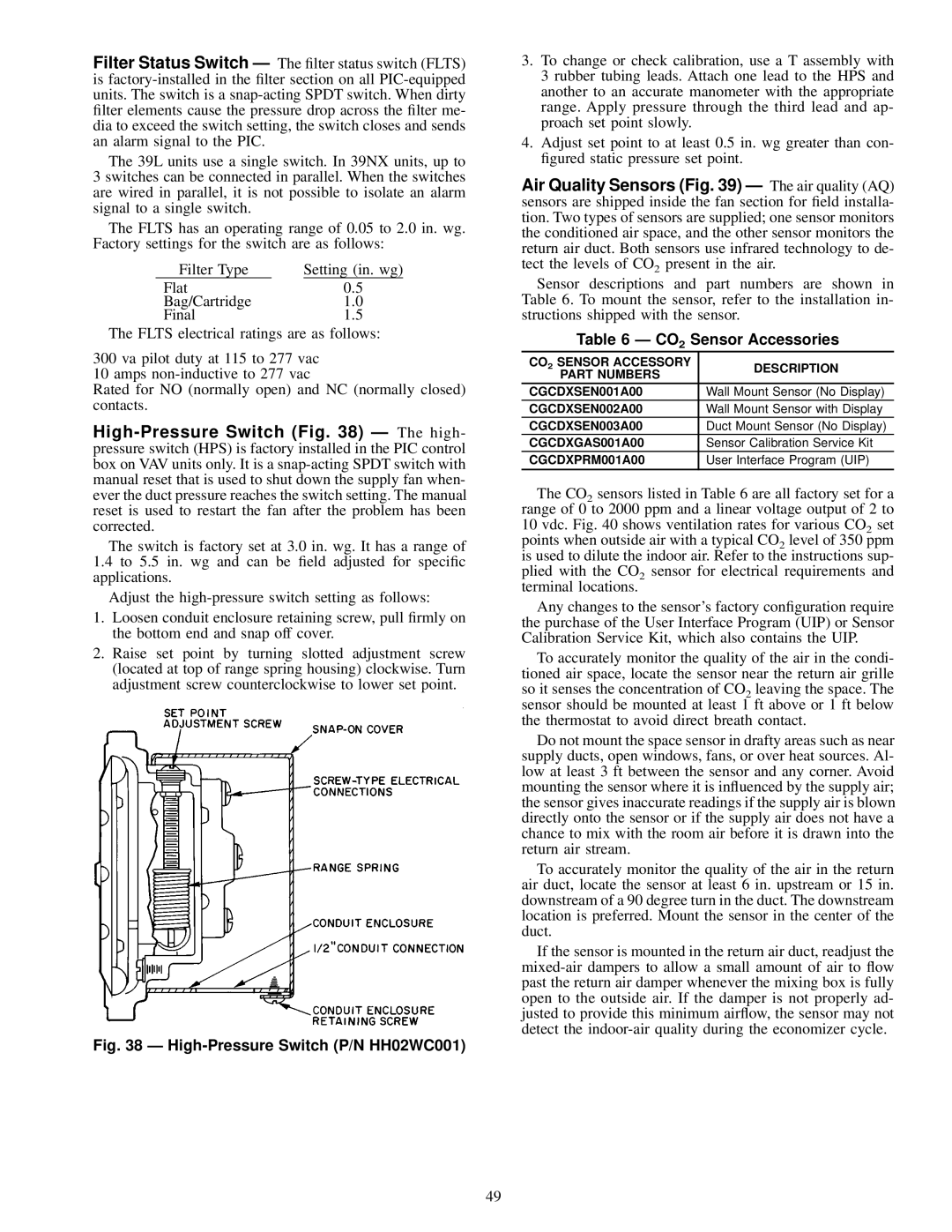
High-Pressure Switch (Fig. 38) Ð The high- pressure switch (HPS) is factory installed in the PIC control box on VAV units only. It is a snap-acting SPDT switch with manual reset that is used to shut down the supply fan when- ever the duct pressure reaches the switch setting. The manual reset is used to restart the fan after the problem has been corrected.

The switch is factory set at 3.0 in. wg. It has a range of

1.4to 5.5 in. wg and can be ®eld adjusted for speci®c applications.

Adjust the high-pressure switch setting as follows:

1.Loosen conduit enclosure retaining screw, pull ®rmly on the bottom end and snap off cover.

2.Raise set point by turning slotted adjustment screw (located at top of range spring housing) clockwise. Turn adjustment screw counterclockwise to lower set point.

Fig. 38 Ð High-Pressure Switch (P/N HH02WC001)

3.To change or check calibration, use a T assembly with 3 rubber tubing leads. Attach one lead to the HPS and another to an accurate manometer with the appropriate range. Apply pressure through the third lead and ap- proach set point slowly.

4.Adjust set point to at least 0.5 in. wg greater than con- ®gured static pressure set point.

Air Quality Sensors (Fig. 39) Ð The air quality (AQ) sensors are shipped inside the fan section for ®eld installa- tion. Two types of sensors are supplied; one sensor monitors the conditioned air space, and the other sensor monitors the return air duct. Both sensors use infrared technology to de- tect the levels of CO2 present in the air.

Sensor descriptions and part numbers are shown in Table 6. To mount the sensor, refer to the installation in- structions shipped with the sensor.

Table 6 Ð CO2 Sensor Accessories

CO2 SENSOR ACCESSORY

DESCRIPTION

PART NUMBERS


CGCDXSEN001A00

Wall Mount Sensor (No Display)

CGCDXSEN002A00

Wall Mount Sensor with Display

CGCDXSEN003A00

Duct Mount Sensor (No Display)

CGCDXGAS001A00

Sensor Calibration Service Kit

CGCDXPRM001A00

User Interface Program (UIP)


The CO2 sensors listed in Table 6 are all factory set for a range of 0 to 2000 ppm and a linear voltage output of 2 to 10 vdc. Fig. 40 shows ventilation rates for various CO2 set points when outside air with a typical CO2 level of 350 ppm is used to dilute the indoor air. Refer to the instructions sup- plied with the CO2 sensor for electrical requirements and terminal locations.

Any changes to the sensor's factory con®guration require the purchase of the User Interface Program (UIP) or Sensor Calibration Service Kit, which also contains the UIP.

To accurately monitor the quality of the air in the condi- tioned air space, locate the sensor near the return air grille so it senses the concentration of CO2 leaving the space. The sensor should be mounted at least 1 ft above or 1 ft below the thermostat to avoid direct breath contact.

Do not mount the space sensor in drafty areas such as near supply ducts, open windows, fans, or over heat sources. Al- low at least 3 ft between the sensor and any corner. Avoid mounting the sensor where it is in¯uenced by the supply air; the sensor gives inaccurate readings if the supply air is blown directly onto the sensor or if the supply air does not have a chance to mix with the room air before it is drawn into the return air stream.

To accurately monitor the quality of the air in the return air duct, locate the sensor at least 6 in. upstream or 15 in. downstream of a 90 degree turn in the duct. The downstream location is preferred. Mount the sensor in the center of the duct.

If the sensor is mounted in the return air duct, readjust the mixed-air dampers to allow a small amount of air to ¯ow past the return air damper whenever the mixing box is fully open to the outside air. If the damper is not properly ad- justed to provide this minimum air¯ow, the sensor may not detect the indoor-air quality during the economizer cycle.

49

Page 49
Image 49
Carrier 39L specifications CO2 Sensor Accessories, CGCDXSEN002A00, CGCDXSEN003A00, CGCDXGAS001A00, CGCDXPRM001A00

39L specifications

The Carrier 39L is a cutting-edge air conditioning unit designed for both residential and commercial applications, providing exceptional cooling and heating performance. Equipped with advanced technologies, this system ensures optimal climate control while maintaining energy efficiency.

One of the standout features of the Carrier 39L is its inverter technology. This innovation allows the system to adjust its compressor speed based on the ambient temperature, which results in a significant reduction in energy consumption. By operating at varying capacities rather than a fixed output, the 39L can maintain a consistent temperature, enhancing comfort while lowering electricity bills.

The Carrier 39L also includes a high-efficiency air filtration system, designed to capture dust, allergens, and other airborne particles. This not only improves indoor air quality but also promotes a healthier living environment. The filtration system is complemented by anti-bacterial treatment, ensuring that the air circulated within your space is both clean and refreshing.

In terms of design, the Carrier 39L boasts a sleek and compact form factor, making it easy to integrate into various settings, from homes to offices. Its quiet operation is another notable feature, as it minimizes noise levels, allowing occupants to enjoy a serene atmosphere without disruptive sound.

Further enhancing convenience, the Carrier 39L comes equipped with smart connectivity options. Users can control the unit remotely via a smartphone app, making it easy to adjust settings, program schedules, and monitor energy usage from anywhere. This feature not only improves user experience but also supports energy-saving practices.

Durability is also a key characteristic of the Carrier 39L. Constructed with high-quality materials and coated with corrosion-resistant treatments, the unit is built to withstand various environmental conditions. This ensures long-lasting performance and reduces the need for frequent maintenance.

Overall, the Carrier 39L is a versatile, efficient, and user-friendly air conditioning solution. Its blend of advanced technologies, energy-saving capabilities, and robust design makes it an ideal choice for those seeking reliable climate control in their spaces. Whether for residential comfort or commercial necessity, the Carrier 39L stands out as a leader in modern air conditioning.