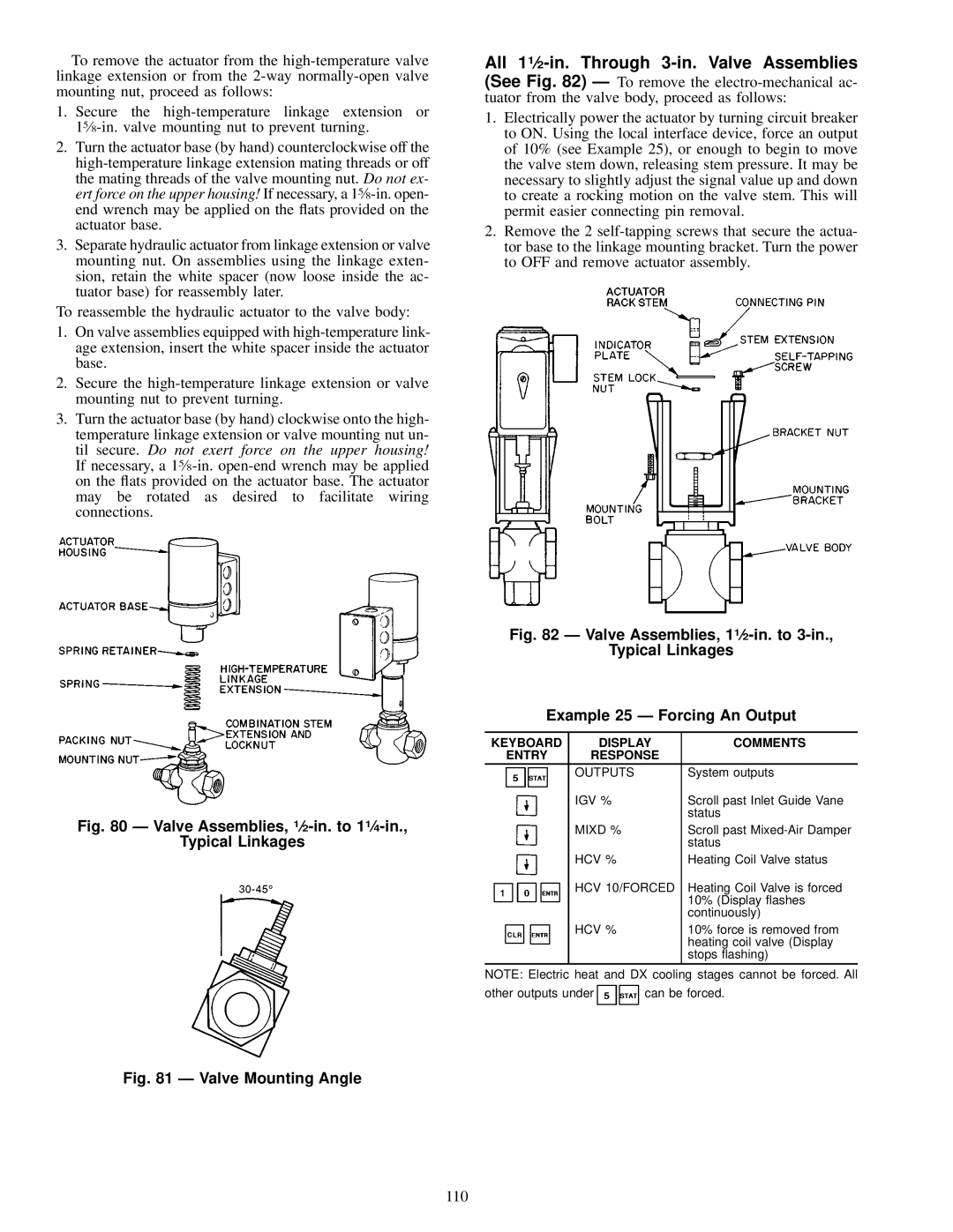
To remove the actuator from the high-temperature valve linkage extension or from the 2-way normally-open valve mounting nut, proceed as follows:

1.Secure the high-temperature linkage extension or 15¤8-in. valve mounting nut to prevent turning.

2.Turn the actuator base (by hand) counterclockwise off the high-temperature linkage extension mating threads or off the mating threads of the valve mounting nut. Do not ex- ert force on the upper housing! If necessary, a 15¤8-in. open- end wrench may be applied on the ¯ats provided on the actuator base.

3.Separate hydraulic actuator from linkage extension or valve mounting nut. On assemblies using the linkage exten- sion, retain the white spacer (now loose inside the ac- tuator base) for reassembly later.

To reassemble the hydraulic actuator to the valve body:

1.On valve assemblies equipped with high-temperature link- age extension, insert the white spacer inside the actuator base.

2.Secure the high-temperature linkage extension or valve mounting nut to prevent turning.

3.Turn the actuator base (by hand) clockwise onto the high- temperature linkage extension or valve mounting nut un- til secure. Do not exert force on the upper housing! If necessary, a 15¤8-in. open-end wrench may be applied on the ¯ats provided on the actuator base. The actuator may be rotated as desired to facilitate wiring connections.

All 11¤2-in. Through 3-in. Valve Assemblies (See Fig. 82) Ð To remove the electro-mechanical ac- tuator from the valve body, proceed as follows:

1.Electrically power the actuator by turning circuit breaker to ON. Using the local interface device, force an output of 10% (see Example 25), or enough to begin to move the valve stem down, releasing stem pressure. It may be necessary to slightly adjust the signal value up and down to create a rocking motion on the valve stem. This will permit easier connecting pin removal.

2.Remove the 2 self-tapping screws that secure the actua- tor base to the linkage mounting bracket. Turn the power to OFF and remove actuator assembly.


Fig. 82 Ð Valve Assemblies, 11¤2-in. to 3-in.,


Typical Linkages


Example 25 Ð Forcing An Output


KEYBOARD

DISPLAY

COMMENTS


ENTRY

RESPONSE


OUTPUTS

System outputs


IGV %

Scroll past Inlet Guide Vane

Fig. 80 Ð Valve Assemblies, 1¤2-in. to 11¤4-in.,


status

MIXD %

Scroll past Mixed-Air Damper

Typical Linkages


status


HCV %

Heating Coil Valve status


HCV 10/FORCED

Heating Coil Valve is forced


10% (Display ¯ashes


continuously)


HCV %

10% force is removed from


heating coil valve (Display


stops ¯ashing)

NOTE: Electric heat and DX cooling stages cannot be forced. All

other outputs under can be forced.

Fig. 81 Ð Valve Mounting Angle

110

Page 110
Image 110
Carrier 39L specifications Typical Linkages, Example 25 Ð Forcing An Output, Igv %, HCV 10/FORCED

39L specifications

The Carrier 39L is a cutting-edge air conditioning unit designed for both residential and commercial applications, providing exceptional cooling and heating performance. Equipped with advanced technologies, this system ensures optimal climate control while maintaining energy efficiency.

One of the standout features of the Carrier 39L is its inverter technology. This innovation allows the system to adjust its compressor speed based on the ambient temperature, which results in a significant reduction in energy consumption. By operating at varying capacities rather than a fixed output, the 39L can maintain a consistent temperature, enhancing comfort while lowering electricity bills.

The Carrier 39L also includes a high-efficiency air filtration system, designed to capture dust, allergens, and other airborne particles. This not only improves indoor air quality but also promotes a healthier living environment. The filtration system is complemented by anti-bacterial treatment, ensuring that the air circulated within your space is both clean and refreshing.

In terms of design, the Carrier 39L boasts a sleek and compact form factor, making it easy to integrate into various settings, from homes to offices. Its quiet operation is another notable feature, as it minimizes noise levels, allowing occupants to enjoy a serene atmosphere without disruptive sound.

Further enhancing convenience, the Carrier 39L comes equipped with smart connectivity options. Users can control the unit remotely via a smartphone app, making it easy to adjust settings, program schedules, and monitor energy usage from anywhere. This feature not only improves user experience but also supports energy-saving practices.

Durability is also a key characteristic of the Carrier 39L. Constructed with high-quality materials and coated with corrosion-resistant treatments, the unit is built to withstand various environmental conditions. This ensures long-lasting performance and reduces the need for frequent maintenance.

Overall, the Carrier 39L is a versatile, efficient, and user-friendly air conditioning solution. Its blend of advanced technologies, energy-saving capabilities, and robust design makes it an ideal choice for those seeking reliable climate control in their spaces. Whether for residential comfort or commercial necessity, the Carrier 39L stands out as a leader in modern air conditioning.