Field Wiring

NOTE: The relay furnished is a SPDT relay with silver cadmium ox- ide contacts, rated as follows:

48 va at 24 vac and .25 power factor

125 va at 115 vac and .25 power factor

125 va at 230 vac and .25 power factor

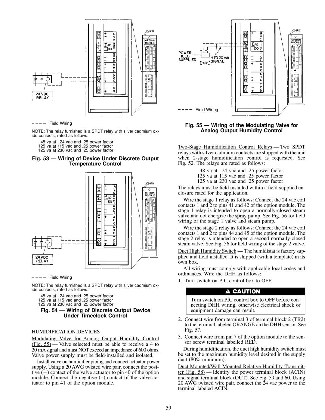
Fig. 53 Ð Wiring of Device Under Discrete Output

Temperature Control

Field Wiring

NOTE: The relay furnished is a SPDT relay with silver cadmium ox- ide contacts, rated as follows:

48 va at 24 vac and .25 power factor

125 va at 115 vac and .25 power factor

125 va at 230 vac and .25 power factor

Fig. 54 Ð Wiring of Discrete Output Device

Under Timeclock Control

HUMIDIFICATION DEVICES

Modulating Valve for Analog Output Humidity Control (Fig. 55) Ð Valve selected must be able to receive a 4 to 20 mA signal and must NOT exceed an impedance of 600 ohms. Valve power supply must be ®eld-installed and isolated.

Install valve on humidi®er piping and connect actuator power supply. Using a 20 AWG twisted wire pair, connect the posi- tive (1) contact of the valve actuator to pin 40 of the option module. Connect the negative (−) contact of the valve ac- tuator to pin 41 of the option module.

Field Wiring

Fig. 55 Ð Wiring of the Modulating Valve for

Analog Output Humidity Control

Two-Stage Humidi®cation Control Relays Ð Two SPDT relays with silver cadmium contacts are shipped with the unit when 2-stage humidi®cation control is requested. See Fig. 52. The relays are rated as follows:

48 va at 24 vac and .25 power factor

125 va at 115 vac and .25 power factor

125 va at 230 vac and .25 power factor

The relays must be ®eld installed within a ®eld-supplied en- closure rated for the application.

Wire the stage 1 relay as follows: Connect the 24 vac coil contacts 1 and 2 to pins 41 and 42 of the option module. The stage 1 relay is intended to open a normally-closed steam valve and not energize the spray pump. See Fig. 56 for ®eld wiring of the stage 1 valve and steam pump.

Wire the stage 2 relay as follows: Connect the 24 vac coil contacts 1 and 2 to pins 44 and 45 of the option module. The stage 2 relay is intended to open a second normally-closed steam valve. See Fig. 56 for ®eld wiring of the stage 2 valve.

Duct High Humidity Switch Ð The humidistat is factory sup- plied and ®eld installed. It is shipped (with a template) in its own box.

All wiring must comply with applicable local codes and ordinances. Wire the DHH as follows:

1. Turn switch on PIC control box to OFF.

Turn switch on PIC control box to OFF before con- necting DHH wiring, otherwise electrical shock or equipment damage can result.

2.Connect wire from terminal 3 of terminal block 2 (TB2) to the terminal labeled ORANGE on the DHH sensor. See Fig. 57.

3.Connect wire from pin 7 of the option module to the sen- sor screw terminal labelled RED.

During humidi®cation, the duct high humidity switch must be set to the maximum humidity level desired in the supply duct (80% minimum).

Duct Mounted/Wall Mounted Relative Humidity Transmit- ter (Fig. 58) Ð Identify the power terminal block (ACIN) and signal terminal block (OUT). See Fig. 59 and 60. Using 20 AWG twisted wire pair, connect the 24 vac power to the terminal labeled ACIN.

59

Page 59
Image 59
Carrier 39L specifications Wiring of Device Under Discrete Output Temperature Control

39L specifications

The Carrier 39L is a cutting-edge air conditioning unit designed for both residential and commercial applications, providing exceptional cooling and heating performance. Equipped with advanced technologies, this system ensures optimal climate control while maintaining energy efficiency.

One of the standout features of the Carrier 39L is its inverter technology. This innovation allows the system to adjust its compressor speed based on the ambient temperature, which results in a significant reduction in energy consumption. By operating at varying capacities rather than a fixed output, the 39L can maintain a consistent temperature, enhancing comfort while lowering electricity bills.

The Carrier 39L also includes a high-efficiency air filtration system, designed to capture dust, allergens, and other airborne particles. This not only improves indoor air quality but also promotes a healthier living environment. The filtration system is complemented by anti-bacterial treatment, ensuring that the air circulated within your space is both clean and refreshing.

In terms of design, the Carrier 39L boasts a sleek and compact form factor, making it easy to integrate into various settings, from homes to offices. Its quiet operation is another notable feature, as it minimizes noise levels, allowing occupants to enjoy a serene atmosphere without disruptive sound.

Further enhancing convenience, the Carrier 39L comes equipped with smart connectivity options. Users can control the unit remotely via a smartphone app, making it easy to adjust settings, program schedules, and monitor energy usage from anywhere. This feature not only improves user experience but also supports energy-saving practices.

Durability is also a key characteristic of the Carrier 39L. Constructed with high-quality materials and coated with corrosion-resistant treatments, the unit is built to withstand various environmental conditions. This ensures long-lasting performance and reduces the need for frequent maintenance.

Overall, the Carrier 39L is a versatile, efficient, and user-friendly air conditioning solution. Its blend of advanced technologies, energy-saving capabilities, and robust design makes it an ideal choice for those seeking reliable climate control in their spaces. Whether for residential comfort or commercial necessity, the Carrier 39L stands out as a leader in modern air conditioning.