Contents
Installation, Operation, Start-Up Instructions
Safety Considerations
Installation
General
Page
IGV
ABX
PIC
VAV
FMB Ð Filter Mixing Box
Direct Expansion
MXB Ð Mixing Box
Normally Closed
Control Box for Remote Mounting
Aotc
AFS
AQ1
AQ2
PIC Section Control Box Component Arrangements, 39L
PIC Section Control Box Component Arrangement, 39NX Sizes
PIC Section Control Box Component Arrangement, 39NX Sizes
Page
Address
Input and Output Points
Unit Wiring Schematic, 39L Sizes 03-35 115 v, Typical
Unit Wiring Schematic, 39L Sizes 03-35 115 v, Typical
Unit Wiring Schematic, 39L Sizes 03-35 115 v, Typical
Unit Wiring Schematic, 39L Sizes 03-35 115 v, Typical
Unit Wiring Schematic, 39L Sizes 03-35 115 v, Typical
Unit Wiring Schematic, 39L Sizes 03-35 115 v, Typical
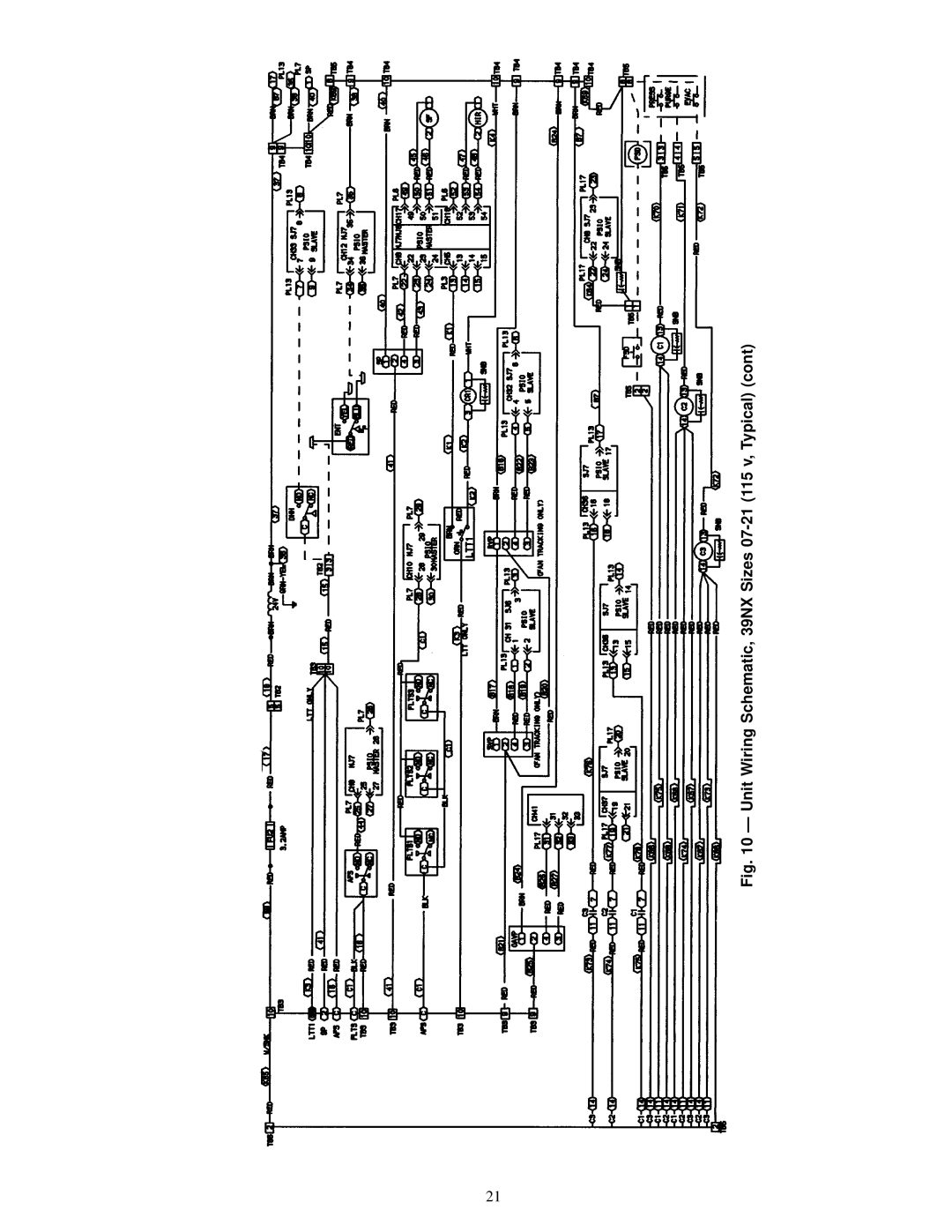
Unit Wiring Schematic, 39NX Sizes 07-21 115 v, Typical
Unit Wiring Schematic, 39NX Sizes 07-21 115 v, Typical
Unit Wiring Schematic, 39NX Sizes 07-21 115 v, Typical
Unit Wiring Schematic, 39NX Sizes 07-21 115 v, Typical
Unit Wiring Schematic, 39NX Sizes 07-21 115 v, Typical
Unit Wiring Schematic, 39NX Sizes 07-21 115 v, Typical
Unit Wiring Schematic, 39NX Sizes 26-92 115 v, Typical
Unit Wiring Schematic, 39NX Sizes 26-92 115 v, Typical
Unit Wiring Schematic, 39NX Sizes 26-92 115 v, Typical
Unit Wiring Schematic, 39NX Sizes 26-92 115 v, Typical
Unit Wiring Schematic, 39NX Sizes 26-92 115 v, Typical
Unit Wiring Schematic, 39NX Sizes 26-92 115 v, Typical
Page
Page
Page
Page
Page
Page
Terminal Signal
Junction Box Connections for Optional Remote Control Box
Valve Assembly Typical
Hot Water Valve Wiring
Duct Static Pressure Probe
Chilled Water Valve Wiring
Nema Ð National Electrical Manufacturers Association
Ohms
Resistance Temperature
Mixed-Air Temperature Sensor HH79NZ021 Installation
Supply/Return Air Temperature Sensor HH79NZ019
Enthalpy Control Settings
COI L Comno
Wall-Mounted Relative Humidity Sensor Fig
Duct-Mounted Relative Humidity Sensor Locations
Air¯ow Switch P/N HK06WC030
CGCDXSEN002A00
CO2 Sensor Accessories
CGCDXSEN003A00
CGCDXGAS001A00
CO2 Concentration PPM
Air Quality CO2 Sensor Wall Mount Version Shown
OAC Pressure Transducers
Manufacturer Part Number
Recommended Sensor Device Wiring
Processor
Sensor Module PIN no
Field Wiring of Sensors
Stroke
Recommended Actuators
Field-Supplied Mixing Box Actuator Signal Wiring
High-Pressure Switch Remove Jumper
HAND/OFF/AUTO Switch Tran Ð Transformer
Evacuation Supply Fan Contactor
Fire Shut Down Terminal Block
Pres
Single-Pole, Double-Throw Spdt Relay
Wiring of Device Under Discrete Output Temperature Control
Wiring of Two-Stage Humidication Control Relays
Duct Mounted Relative Humidity Transmitter Wiring
Air Quality and Oavp Sensor Wiring
Wiring of Return Fan Volume Control With IGVs
Control System
Pulse-Type Meter Wiring
CCN Communication Wiring
Air Handling Unit
AHU
Relay Module
Outdoor Air Thermostat
Local Interface Device Key Usage
Function USE Keys
Operative USE Keys
Functions and Subfunctions
Status History Schedule Service Set Point Test
SUB Function Number
Oavp
Operation Keyboard Display Description Entry
Control Operation
Status
Keyboard Directory
Inputs
VAV
Direct Expansion Oavp Ð Outside Air Velocity Pressure
AIRQUAL1
SET Point
Quick Test
History
Example 1 Ð Reading Alarm Codes
Example 2 Ð Reading Current Operating Modes
Keyboard Display Comments Entry Response
Display Codes
Alarms
Force States
Display Description
Example 3 Ð Forcing An Input Value
State of Items Controlled
Example 4 Ð Forcing An Output Value
Relay Stages
Example 6 Ð Logging On and Logging Off Service Function
Example 5 Ð Using Quick Test
Keyboard Display Comments Entry Response To LOG on
To LOG OFF
Service Conguration Ranges and Defaults
Analog Output Temperature Control
Example 7 Ð Reading and Changing Factory Congurations
Example 8 Ð Conguration of Measurements
Example 9 Ð User Congurations
Example 11 Ð Conguration of Space Temperature Reset
Example 10 Ð Conguration of Heating Coil
Example 12 Ð Conguration of Loadshed
Example 14 Ð Conguration of Alarm Limits
Example 15 Ð Conguration of Analog Temperature Control
Example 13 Ð Conguration of Fan Tracking
Example 17 Ð Service History Conguration
Example 16 Ð Conguration of Discrete Temperature Control
Example 18 Ð Service/Maintenance Alarm Conguration
Set Point Ranges and Defaults
Example 21 Ð Setting of Time and Date
Example 22 Ð Setting Daylight Savings Time
Example 20 Ð Reading and Changing System Set Points
Schedule I Sample Time Schedule
Example 23 Ð Setting of Holidays
Example 24 Ð Using the Schedule Function
Keyboard Display Comment Entry Response Programming Period
Period 1 Dene schedule period
For this example, Period 6 is used for holiday only
Control Operating Sequence
Constant Volume and Variable Air Volume Units
Page
Page
OAT Ð Outdoor-Air Temperature
MAT Ð Mixed-Air Temperature
IAQ
Indoor-Air Quality
Constant Volume Units Only
RAT Ð Return-Air
CCV Ð Cooling Coil Valve
DX Submaster Gain Control Operation
Variable Air Volume Units Only
Page
OAC
Outside Air
Constant Outside Air
Oavp Ð Outside Air Velocity Pressure
102
Initial Check
START-UP
Keyboard Display COMMENTS/ACTION Entry Response
Test of Input Signals
Following
Keyboard Display COMMENTS/ACTION Entry Response FSD NRM
For Variable Air Volume Units
Test of Output Signals
Electric Heater Test
Test of Output Options Using Option Module
Direct Expansion DX Cooling Test
Control Loop Checkout
Digital DC Volt Meter vs DC Milliamp Meter
DC Milliamps DC Voltage
Recommended Gain Starting Valves
Valve Troubleshooting
Example 25 Ð Forcing An Output
Typical Linkages
IGV %
HCV 10/FORCED
Control Module Troubleshooting
Example 26 Ð Heating Coil Valve Test Way Normally Open
Exit Test
Dsio
Problem Possible Cause Corrective Action
Unit Troubleshooting
HCV, CCV, IGV
IAQ features
OAC malfunctioning
Malfunctioning
Metric Conversion Chart