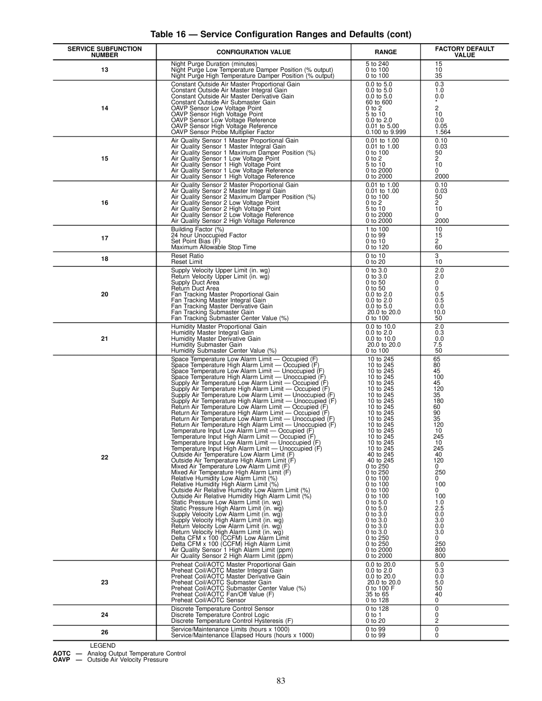
SERVICE SUBFUNCTION | | CONFIGURATION VALUE | RANGE | FACTORY DEFAULT |
| NUMBER | | VALUE |
| | | |
| 13 | | Night Purge Duration (minutes) | 5 to 240 | 15 |
| | Night Purge Low Temperature Damper Position (% output) | 0 to 100 | 10 |
| | | Night Purge High Temperature Damper Position (% output) | 0 to 100 | 35 |
| | | Constant Outside Air Master Proportional Gain | 0.0 to 5.0 | 0.3 |
| | | Constant Outside Air Master Integral Gain | 0.0 to 5.0 | 1.0 |
| | | Constant Outside Air Master Derivative Gain | 0.0 to 5.0 | 0.0 |
| 14 | | Constant Outside Air Submaster Gain | 60 to 600 | * |
| | OAVP Sensor Low Voltage Point | 0 to 2 | 2 |
| | | OAVP Sensor High Voltage Point | 5 to 10 | 10 |
| | | OAVP Sensor Low Voltage Reference | 0.0 to 2.0 | 0.0 |
| | | OAVP Sensor High Voltage Reference | 0.01 to 5.00 | 0.05 |
| | | OAVP Sensor Probe Multiplier Factor | 0.100 to 9.999 | 1.564 |
| | | Air Quality Sensor 1 Master Proportional Gain | 0.01 to 1.00 | 0.10 |
| | | Air Quality Sensor 1 Master Integral Gain | 0.01 to 1.00 | 0.03 |
| 15 | | Air Quality Sensor 1 Maximum Damper Position (%) | 0 to 100 | 50 |
| | Air Quality Sensor 1 Low Voltage Point | 0 to 2 | 2 |
| | | Air Quality Sensor 1 High Voltage Point | 5 to 10 | 10 |
| | | Air Quality Sensor 1 Low Voltage Reference | 0 to 2000 | 0 |
| | | Air Quality Sensor 1 High Voltage Reference | 0 to 2000 | 2000 |
| | | Air Quality Sensor 2 Master Proportional Gain | 0.01 to 1.00 | 0.10 |
| | | Air Quality Sensor 2 Master Integral Gain | 0.01 to 1.00 | 0.03 |
| 16 | | Air Quality Sensor 2 Maximum Damper Position (%) | 0 to 100 | 50 |
| | Air Quality Sensor 2 Low Voltage Point | 0 to 2 | 2 |
| | | Air Quality Sensor 2 High Voltage Point | 5 to 10 | 10 |
| | | Air Quality Sensor 2 Low Voltage Reference | 0 to 2000 | 0 |
| | | Air Quality Sensor 2 High Voltage Reference | 0 to 2000 | 2000 |
| | | Building Factor (%) | 1 to 100 | 10 |
| 17 | | 24 hour Unoccupied Factor | 0 to 99 | 15 |
| | Set Point Bias (F) | 0 to 10 | 2 |
| | |
| | | Maximum Allowable Stop Time | 0 to 120 | 60 |
| | | | | |
| 18 | | Reset Ratio | 0 to 10 | 3 |
| | Reset Limit | 0 to 20 | 10 |
| | |
| | | Supply Velocity Upper Limit (in. wg) | 0 to 3.0 | 2.0 |
| | | Return Velocity Upper Limit (in. wg) | 0 to 3.0 | 2.0 |
| | | Supply Duct Area | 0 to 50 | 0 |
| 20 | | Return Duct Area | 0 to 50 | 0 |
| | Fan Tracking Master Proportional Gain | 0.0 to 2.0 | 0.5 |
| | | Fan Tracking Master Integral Gain | 0.0 to 2.0 | 0.5 |
| | | Fan Tracking Master Derivative Gain | 0.0 to 5.0 | 0.0 |
| | | Fan Tracking Submaster Gain | −20.0 to 20.0 | 10.0 |
| | | Fan Tracking Submaster Center Value (%) | 0 to 100 | 50 |
| | | Humidity Master Proportional Gain | 0.0 to 10.0 | 2.0 |
| 21 | | Humidity Master Integral Gain | 0.0 to 2.0 | 0.3 |
| | Humidity Master Derivative Gain | 0.0 to 10.0 | 0.0 |
| | | Humidity Submaster Gain | −20.0 to 20.0 | 7.5 |
| | | Humidity Submaster Center Value (%) | 0 to 100 | 50 |
| | | Space Temperature Low Alarm Limit Ð Occupied (F) | −10 to 245 | 65 |
| | | Space Temperature High Alarm Limit Ð Occupied (F) | −10 to 245 | 80 |
| | | Space Temperature Low Alarm Limit Ð Unoccupied (F) | −10 to 245 | 45 |
| | | Space Temperature High Alarm Limit Ð Unoccupied (F) | −10 to 245 | 100 |
| | | Supply Air Temperature Low Alarm Limit Ð Occupied (F) | −10 to 245 | 45 |
| | | Supply Air Temperature High Alarm Limit Ð Occupied (F) | −10 to 245 | 120 |
| | | Supply Air Temperature Low Alarm Limit Ð Unoccupied (F) | −10 to 245 | 35 |
| | | Supply Air Temperature High Alarm Limit Ð Unoccupied (F) | −10 to 245 | 180 |
| | | Return Air Temperature Low Alarm Limit Ð Occupied (F) | −10 to 245 | 60 |
| | | Return Air Temperature High Alarm Limit Ð Occupied (F) | −10 to 245 | 90 |
| | | Return Air Temperature Low Alarm Limit Ð Unoccupied (F) | −10 to 245 | 35 |
| | | Return Air Temperature High Alarm Limit Ð Unoccupied (F) | −10 to 245 | 120 |
| | | Temperature Input Low Alarm Limit Ð Occupied (F) | −10 to 245 | −10 |
| | | Temperature Input High Alarm Limit Ð Occupied (F) | −10 to 245 | 245 |
| | | Temperature Input Low Alarm Limit Ð Unoccupied (F) | −10 to 245 | −10 |
| | | Temperature Input High Alarm Limit Ð Unoccupied (F) | −10 to 245 | 245 |
| 22 | | Outside Air Temperature Low Alarm Limit (F) | −40 to 245 | −40 |
| | Outside Air Temperature High Alarm Limit (F) | −40 to 245 | 120 |
| | |
| | | Mixed Air Temperature Low Alarm Limit (F) | 0 to 250 | 0 |
| | | Mixed Air Temperature High Alarm Limit (F) | 0 to 250 | 250 |
| | | Relative Humidity Low Alarm Limit (%) | 0 to 100 | 0 |
| | | Relative Humidity High Alarm Limit (%) | 0 to 100 | 100 |
| | | Outside Air Relative Humidity Low Alarm Limit (%) | 0 to 100 | 0 |
| | | Outside Air Relative Humidity High Alarm Limit (%) | 0 to 100 | 100 |
| | | Static Pressure Low Alarm Limit (in. wg) | 0 to 5.0 | 1.0 |
| | | Static Pressure High Alarm Limit (in. wg) | 0 to 5.0 | 2.5 |
| | | Supply Velocity Low Alarm Limit (in. wg) | 0 to 3.0 | 0.0 |
| | | Supply Velocity High Alarm Limit (in. wg) | 0 to 3.0 | 3.0 |
| | | Return Velocity Low Alarm Limit (in. wg) | 0 to 3.0 | 0.0 |
| | | Return Velocity High Alarm Limit (in. wg) | 0 to 3.0 | 3.0 |
| | | Delta CFM x 100 (CCFM) Low Alarm Limit | 0 to 250 | 0 |
| | | Delta CFM x 100 (CCFM) High Alarm Limit | 0 to 250 | 250 |
| | | Air Quality Sensor 1 High Alarm Limit (ppm) | 0 to 2000 | 800 |
| | | Air Quality Sensor 2 High Alarm Limit (ppm) | 0 to 2000 | 800 |
| | | Preheat Coil/AOTC Master Proportional Gain | 0.0 to 20.0 | 5.0 |
| | | Preheat Coil/AOTC Master Integral Gain | 0.0 to 2.0 | 0.3 |
| 23 | | Preheat Coil/AOTC Master Derivative Gain | 0.0 to 20.0 | 0.0 |
| | Preheat Coil/AOTC Submaster Gain | −20.0 to 20.0 | −5.0 |
| | | Preheat Coil/AOTC Submaster Center Value (%) | 0 to 100 F | 50 |
| | | Preheat Coil/AOTC Fan/Off Value (F) | 35 to 65 | 40 |
| | | Preheat Coil/AOTC Sensor | 0 to 128 | 0 |
| 24 | | Discrete Temperature Control Sensor | 0 to 128 | 0 |
| | Discrete Temperature Control Logic | 0 to 1 | 0 |
| | | Discrete Temperature Control Hysteresis (F) | 0 to 20 | 2 |
| 26 | | Service/Maintenance Limits (hours x 1000) | 0 to 99 | 0 |
| | Service/Maintenance Elapsed Hours (hours x 1000) | 0 to 99 | 0 |
| | |
| LEGEND | | | |
AOTC | Ð Analog Output Temperature Control | | |
OAVP | Ð Outside Air Velocity Pressure | | | |