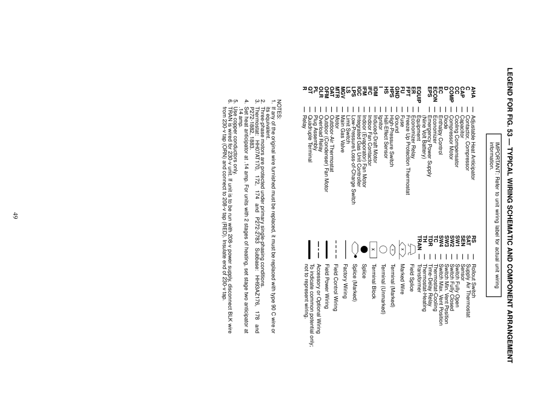
48TF004-007 specifications
The Carrier 48TF004-007 is part of the brand's renowned rooftop unit series, designed to deliver efficient, reliable performance for commercial applications. Ideal for spaces such as offices, retail stores, and small manufacturing facilities, these units encapsulate advanced technology to enhance indoor air quality and optimize climate control.One of the standout features of the Carrier 48TF004-007 units is their variable speed compressor technology. This innovation not only allows for precise temperature control but also reduces energy consumption by modulating the compressor's speed according to the cooling or heating demand. By operating at lower speeds during less demanding conditions, these units significantly decrease energy usage compared to traditional single-speed compressors, contributing to lower utility bills and a reduced carbon footprint.
Energy efficiency is further enhanced with the inclusion of high-performance scroll compressors, which are known for their reliable operation and quiet performance. Coupled with an Energy Efficiency Ratio (EER) that meets or exceeds industry standards, these systems are designed to offer economical operation without sacrificing comfort.
Incorporating smart controls and connectivity features, the Carrier 48TF004-007 units allow for easy integration into building management systems (BMS). This enhances the ability to monitor and manage energy usage in real time, further promoting efficiency. The units are also compatible with various thermostat options, allowing for user-friendly operation and customization of settings.
Another significant characteristic of the Carrier 48TF004-007 is its durable construction. Built with galvanized steel and powder-coated finishes, these units are designed to withstand the rigors of outdoor installation, ensuring long-lasting performance even in harsh weather conditions. Additionally, the units come equipped with advanced filtration systems that help improve indoor air quality by effectively removing dust, allergens, and other particulate matter from the air.
Maintenance is simplified with the Carrier 48TF004-007, providing easy access to vital components, which supports reduced downtime and service costs. The units also feature low operating sound levels, making them suitable for noise-sensitive applications.
In conclusion, the Carrier 48TF004-007 rooftop units stand out for their energy efficiency, advanced technology, durability, and ease of maintenance, making them an excellent choice for any commercial space looking to enhance comfort while effectively managing operational costs.

