SUPPLY AIR

TEMPERATURE

SENSOR

MOUNTING

LOCATION

SUPPLY AIR

TEMPERATURE

SENSOR

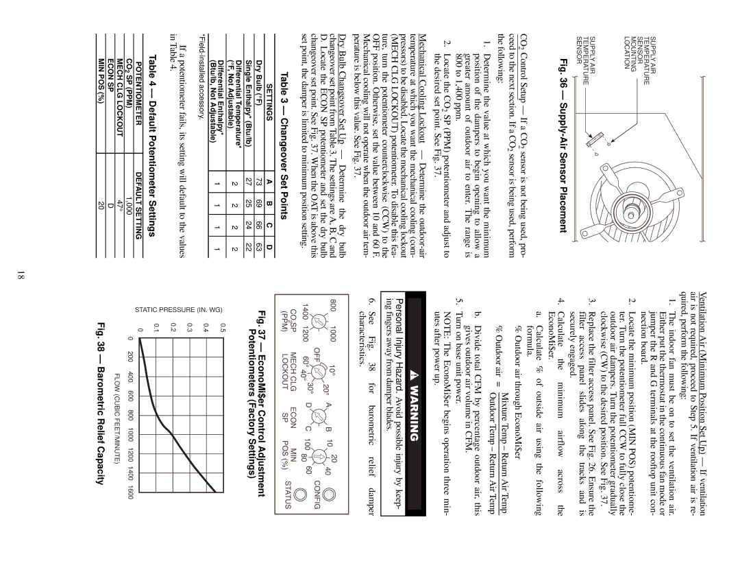
Fig. 36 — Supply-Air Sensor Placement

CO2 Control Setup — If a CO 2 sensor is not being used, pro-

ceed to the next section. If a CO2 sensor is being used, perform the following:

1.Determine the value at which you want the minimum position of the dampers to begin opening to allow a greater amount of outdoor air to enter. The range is 800 to 1,400 ppm.

2.Locate the CO2 SP (PPM) potentiometer and adjust to the desired set point. See Fig. 37.

Mechanical Cooling Lockout — Determine the outdoor-air temperature at which you want the mechanical cooling (com- pressors) to be disabled. Locate the mechanical cooling lockout (MECH CLG LOCKOUT) potentiometer. To disable this fea- ture, turn the potentiometer counterclockwise (CCW) to the OFF position. Otherwise, set the value between 10 and 60 F. Mechanical cooling will not operate when the outdoor air tem- perature is below this value. See Fig. 37.

Dry Bulb Changeover Set Up — Determine the dry bulb changeover set point from Table 3. The settings are A, B, C and D. Locate the ECON SP potentiometer and set the dry bulb changeover set point. See Fig. 37. When the OAT is above this set point, the damper is limited to minimum position setting.

Table 3 — Chan geover Set Points

SETTINGS

A

B

C

D

Dry Bulb (°F)

73

69

66

63

Single Enthalpy* (Btu/lb)

27

25

24

22

Differential Temperature*

2

2

2

2

(°F, Not Adjustable)


Differential Enthalpy*

1

1

1

1

(Btu/lb, Not Adjustable)


*Field-installed accessory.


If a potentiometer fails, its setting will default to the values in Table 4.

Table 4 — Default Potentiometer Settin gs

POTENTIOMETER

DEFAULT SETTING

CO2 SP (PPM)

1,000

MECH CLG LOCKOUT

47°

ECON SP

D

MIN POS (%)

20

Ventilation Air (Minimum Position Set Up) — If ventilation air is not required, proceed to Step 5. If ventilation air is re- quired, perform the following:

1.The indoor fan must be on to set the ventilation air. Either put the thermostat in the continuous fan mode or jumper the R and G terminals at the rooftop unit con- nection board.

2.Locate the minimum position (MIN POS) potentiome- ter. Turn the potentiometer full CCW to fully close the outdoor air dampers. Turn the potentiometer gradually clockwise (CW) to the desired position. See Fig. 37.

3.Replace the filter access panel. See Fig. 26. Ensure the filter access panel slides along the tracks and is securely engaged.

4.Calculate the minimum airflow across the EconoMi$er.

a.Calculate % of outside air using the following formula.

%Outdoor air through EconoMi$er

%Outdoor air = Mixture Temp – Return Air Temp Outdoor Temp – Return Air Temp

b.Divide total CFM by percentage outdoor air, this gives outdoor air volume in CFM.

5.Turn on base unit power.

NOTE: The EconoMi$er begins operation three min- utes after power up.

Personal Injury Hazard. Avoid possible injury by keep- ing fingers away from damper blades.

6. See Fig. 38 for barometric relief damper characteristics.

Fig. 37 — EconoMi$er Control Adjustment Potentiometers (Factory Settings)

WG)

0.5


0.4


(IN.


PRESSURE

0.3


0.2


STATIC

0.1


0


200

400

600

800

1000

1200

1400

1600


0


FLOW (CUBIC FEET/MINUTE)


Fig. 38 — Barometric Relief Capacity

18

Page 18
Image 18
Carrier 48TF004-007 Chan geover Set Points, Default Potentiometer Settin gs, Settings, Mech CLG Lockout Econ SP MIN POS %

48TF004-007 specifications

The Carrier 48TF004-007 is part of the brand's renowned rooftop unit series, designed to deliver efficient, reliable performance for commercial applications. Ideal for spaces such as offices, retail stores, and small manufacturing facilities, these units encapsulate advanced technology to enhance indoor air quality and optimize climate control.

One of the standout features of the Carrier 48TF004-007 units is their variable speed compressor technology. This innovation not only allows for precise temperature control but also reduces energy consumption by modulating the compressor's speed according to the cooling or heating demand. By operating at lower speeds during less demanding conditions, these units significantly decrease energy usage compared to traditional single-speed compressors, contributing to lower utility bills and a reduced carbon footprint.

Energy efficiency is further enhanced with the inclusion of high-performance scroll compressors, which are known for their reliable operation and quiet performance. Coupled with an Energy Efficiency Ratio (EER) that meets or exceeds industry standards, these systems are designed to offer economical operation without sacrificing comfort.

Incorporating smart controls and connectivity features, the Carrier 48TF004-007 units allow for easy integration into building management systems (BMS). This enhances the ability to monitor and manage energy usage in real time, further promoting efficiency. The units are also compatible with various thermostat options, allowing for user-friendly operation and customization of settings.

Another significant characteristic of the Carrier 48TF004-007 is its durable construction. Built with galvanized steel and powder-coated finishes, these units are designed to withstand the rigors of outdoor installation, ensuring long-lasting performance even in harsh weather conditions. Additionally, the units come equipped with advanced filtration systems that help improve indoor air quality by effectively removing dust, allergens, and other particulate matter from the air.

Maintenance is simplified with the Carrier 48TF004-007, providing easy access to vital components, which supports reduced downtime and service costs. The units also feature low operating sound levels, making them suitable for noise-sensitive applications.

In conclusion, the Carrier 48TF004-007 rooftop units stand out for their energy efficiency, advanced technology, durability, and ease of maintenance, making them an excellent choice for any commercial space looking to enhance comfort while effectively managing operational costs.