HUMIDFIER |
(24VAC) |
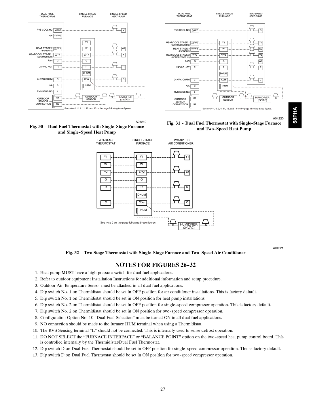
See notes 1, 2, 4, 11, 12, and 13 on the page following these figures.
A04219
Fig. 30 - Dual Fuel Thermostat with Single-Stage Furnace
and Single-Speed Heat Pump
HUMIDFIER |
(24VAC) |
See notes 1, 2, 3, 4, 11, 12, and 14 on the page following these figures.
A04220
Fig. 31 - Dual Fuel Thermostat with Single-Stage Furnace
and Two-Speed Heat Pump
58PHA
See note 2 on the page following these figures. | HUMIDFIER |
| |
| (24VAC) |
A04221
Fig. 32 - Two Stage Thermostat with Single-Stage Furnace and Two-Speed Air Conditioner
NOTES FOR FIGURES
1.Heat pump MUST have a high pressure switch for dual fuel applications.
2.Refer to outdoor equipment Installation Instructions for additional information and setup procedure.
3.Outdoor Air Temperature Sensor must be attached in all dual fuel applications.
4.Dip switch No. 1 on Thermidistat should be set in OFF position for air conditioner installations. This is factory default.
5.Dip switch No. 1 on Thermidistat should be set in ON position for heat pump installations.
6.Dip switch No. 2 on Thermidistat should be set in OFF position for
7.Dip switch No. 2 on Thermidistat should be set in ON position for
8.Configuration Option No. 10 “Dual Fuel Selection” must be turned ON in all dual fuel applications.
9.NO connection should be made to the furnace HUM terminal when using a Thermidistat.
10.The RVS Sensing terminal “L” should not be connected. This is internally used to sense defrost operation.
11.DO NOT SELECT the “FURNACE INTERFACE” or “BALANCE POINT” option on the
12.Dip switch D on Dual Fuel Thermostat should be set in OFF position for
13.Dip switch D on Dual Fuel Thermostat should be set in ON position for
27
