5/16″
(8mm)
(8mm)
5/16″
1 3/4″ (44mm)
1 3/4″ (44mm)
(8mm)
5/16″
(8mm)
5/16″
(44mm) 1 3/4″ (44mm)1 3/4″
A89014
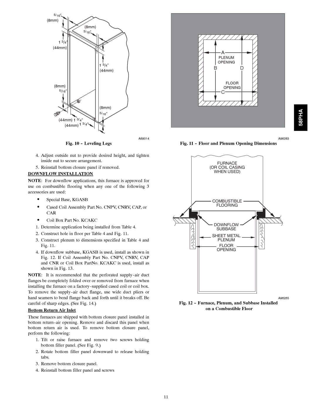
Fig. 10 - Leveling Legs
4.Adjust outside nut to provide desired height, and tighten inside nut to secure arrangement.
5.Reinstall bottom closure panel if removed.
DOWNFLOW INSTALLATION
NOTE: For downflow applications, this furnace is approved for use on combustible flooring when any one of the following 3 accessories are used:
SSpecial Base, KGASB
SCased Coil Assembly Part No. CNPV, CNRV, CAP, or
CAR
SCoil Box Part No. KCAKC
1.Determine application being installed from Table 4.
2.Construct hole in floor per Table 4 and Fig. 11.
3.Construct plenum to dimensions specified in Table 4 and Fig. 11.
4.If downflow subbase, KGASB is used, install as shown in Fig. 12. If Coil Assembly Part No. CNPV, CNRV, CAP and CNR or Coil Box PartNo. KCAKC is used, install as shown in Fig. 13.
NOTE: It is recommended that the perforated
Bottom Return Air Inlet
These furnaces are shipped with bottom closure panel installed in bottom
1.Tilt or raise furnace and remove two screws holding bottom filler panel. (See Fig. 9.)
2.Rotate bottom filler panel downward to release holding tabs.
3.Remove bottom closure panel.
4.Reinstall bottom filler panel and screws
| A |
| PLENUM |
| OPENING |
B | D |
| FLOOR |
| OPENING |
| C |
58PHA
A96283
Fig. 11 - Floor and Plenum Opening Dimensions
FURNACE
(OR COIL CASING
WHEN USED)
COMBUSTIBLE
FLOORING
DOWNFLOW |
SUBBASE |
SHEET METAL |
PLENUM |
FLOOR |
OPENING |
A96285
Fig. 12 - Furnace, Plenum, and Subbase Installed on a Combustible Floor
11
