of at least 2 in.2/1,000 Btuh (4,400 mm2/kW) of total input rating of all gas appliances.
2.An attic or crawlspace may be considered a space that freely communicates with the outdoors provided there are
adequate permanent ventilation openings directly to outdoors having free area of at least
3.In spaces that use the Indoor Combustion Air Method, infiltration should be adequate to provide air for combustion, permanent ventilation and dilution of flue gases. However, in buildings with unusually tight construction, additional air MUST be provided using the methods described in the Outdoor Combustion Air Method section.
Unusually tight construction is defined as construction with:
|
| a. Walls and ceilings exposed to the outdoors have a | |||||||||||||||||
|
| continuous, sealed vapor barrier. Openings are gasketed | |||||||||||||||||
58PHA |
| ||||||||||||||||||
| or sealed and |
|
|
|
|
|
|
|
|
|
|
| |||||||
|
|
|
| ||||||||||||||||
CIRCULATING AIR |
| VENT THROUGH ROOF | |||||||||||||||||
|
|
| DUCTS |
|
|
|
|
|
|
|
|
|
|
|
| ||||
|
|
|
|
|
|
|
|
|
|
|
|
|
|
|
|
|
|
|
|
|
|
|
|
|
|
|
|
|
|
|
|
|
|
|
|
|
|
|
|
|
|
|
|
|
|
|
|
|
|
|
|
|
|
|
|
|
|
|
|
|
|
|
|
|
|
|
|
|
|
|
|
|
|
|
|
|
|
|
|
|
|
|
|
|
|
|
|
| AIR |
|
|
|
|
|
|
|
| ||
|
|
|
|
|
|
|
|
|
|
|
| 12" |
| MAX (305mm) | |||||
|
|
|
|
|
|
|
|
|
|
|
|
| |||||||
|
|
|
|
|
|
|
|
|
|
|
| ||||||||
|
|
|
|
|
|
|
|
| COMBUSTIONOFFRONT IN.3LEASTATBESHALL |
|
|
|
|
|
|
| IN. | ||
|
|
|
|
|
|
|
|
|
|
|
|
|
|
|
| ||||
|
|
|
|
|
|
|
|
|
|
|
|
| 1 SQ |
| |||||
|
|
|
|
|
|
|
|
|
|
|
|
| |||||||
|
|
|
|
|
|
|
|
|
|
|
|
| |||||||
|
|
|
|
|
|
|
|
|
|
|
|
| |||||||
|
|
|
|
|
|
|
|
|
|
|
|
| |||||||
|
|
|
|
|
|
|
|
|
|
|
|
| PER 1000 | ||||||
|
|
|
|
|
|
|
|
|
|
|
|
| |||||||
|
|
|
|
|
|
|
|
|
|
|
|
| |||||||
|
|
|
|
|
|
|
|
|
|
|
|
| BTUH* IN DOOR | ||||||
|
|
|
|
|
|
|
|
|
|
|
|
| OR WALL | ||||||
|
| INTERIOR |
|
|
|
|
|
|
|
|
| UNCONFINED | |||||||
|
|
|
|
|
|
|
|
|
|
| |||||||||
|
|
|
|
|
|
|
|
|
|
| SPACE | ||||||||
|
| HEATED |
|
|
|
|
|
|
|
|
| ||||||||
|
| SPACE |
|
|
|
|
|
|
|
|
|
|
|
|
|
|
|
| |
|
|
|
|
|
|
|
|
|
|
|
|
| 6" MIN (152mm) | ||||||
|
|
|
|
|
|
|
|
| CLEARANCEIN OPENINGS |
|
|
| (FRONT)Ü | ||||||
|
|
|
|
|
|
|
|
|
|
|
| 1 SQ IN. | |||||||
|
|
|
|
|
|
|
|
|
|
|
|
| PER 1000 | ||||||
|
|
|
|
|
|
|
|
|
|
|
|
| BTUH* IN DOOR | ||||||
|
|
|
|
|
|
|
|
|
|
|
|
| |||||||
|
|
|
|
|
|
|
|
|
|
|
|
| |||||||
|
|
|
|
|
|
|
|
|
|
|
|
| OR WALL | ||||||
|
|
|
|
|
|
|
|
|
|
|
|
| |||||||
|
|
|
|
|
|
|
|
|
|
|
|
| |||||||
|
|
|
|
|
|
|
|
|
|
|
|
| |||||||
|
|
|
|
|
|
|
|
|
|
|
|
| |||||||
|
|
|
|
|
|
|
|
|
|
|
|
|
|
|
|
|
|
|
|
|
|
|
|
|
|
|
|
|
|
|
|
|
|
|
|
|
|
|
|
|
|
|
|
|
|
|
|
|
|
|
|
|
|
|
|
|
|
|
|
|
|
|
|
|
|
|
|
|
|
|
|
|
|
|
|
|
|
|
|
|
|
|
|
|
|
|
|
|
|
|
|
|
|
|
|
| 12" MAX (305mm) | ||
|
|
|
|
|
|
|
|
|
|
|
|
|
|
|
|
| |||
|
|
|
|
|
|
|
|
|
|
|
|
|
|
|
|
| |||
|
|
|
|
|
|
|
|
|
|
|
|
|
|
|
|
|
|
|
|
|
|
|
|
|
|
|
|
|
|
|
|
|
|
|
|
|
|
|
|
|
| CIRCULATING AIR DUCTS |
|
|
|
|
|
|
|
|
|
|
| ||||||
|
|
|
|
|
|
|
|
|
|
|
|
|
|
|
|
|
|
|
|
*Minimum opening size is 100 in.2 with minimum dimensions of 3 in. (76 mm).
*Minimum of 3 in. (76 mm), when type
A03175
Fig. 8 - Air for Combustion, Ventilation, and Dilution from
Indoors
b.Doors and openable windows are weatherstripped and
c.Other openings are caulked or sealed. These include joints around window and door frames, between sole plates and floors, between
Combination of Indoor and Outdoor Air
1.Indoor openings shall comply with the Indoor Combustion Air Method below and,
2.Outdoor openings shall be located as required in the Outdoor Combustion Air Method menioned previously and,
3.Outdoor openings shall be sized as follows:
a.Calculate the Ratio of all Indoor Space volume divided by required volume for Indoor Combustion Air Method below.
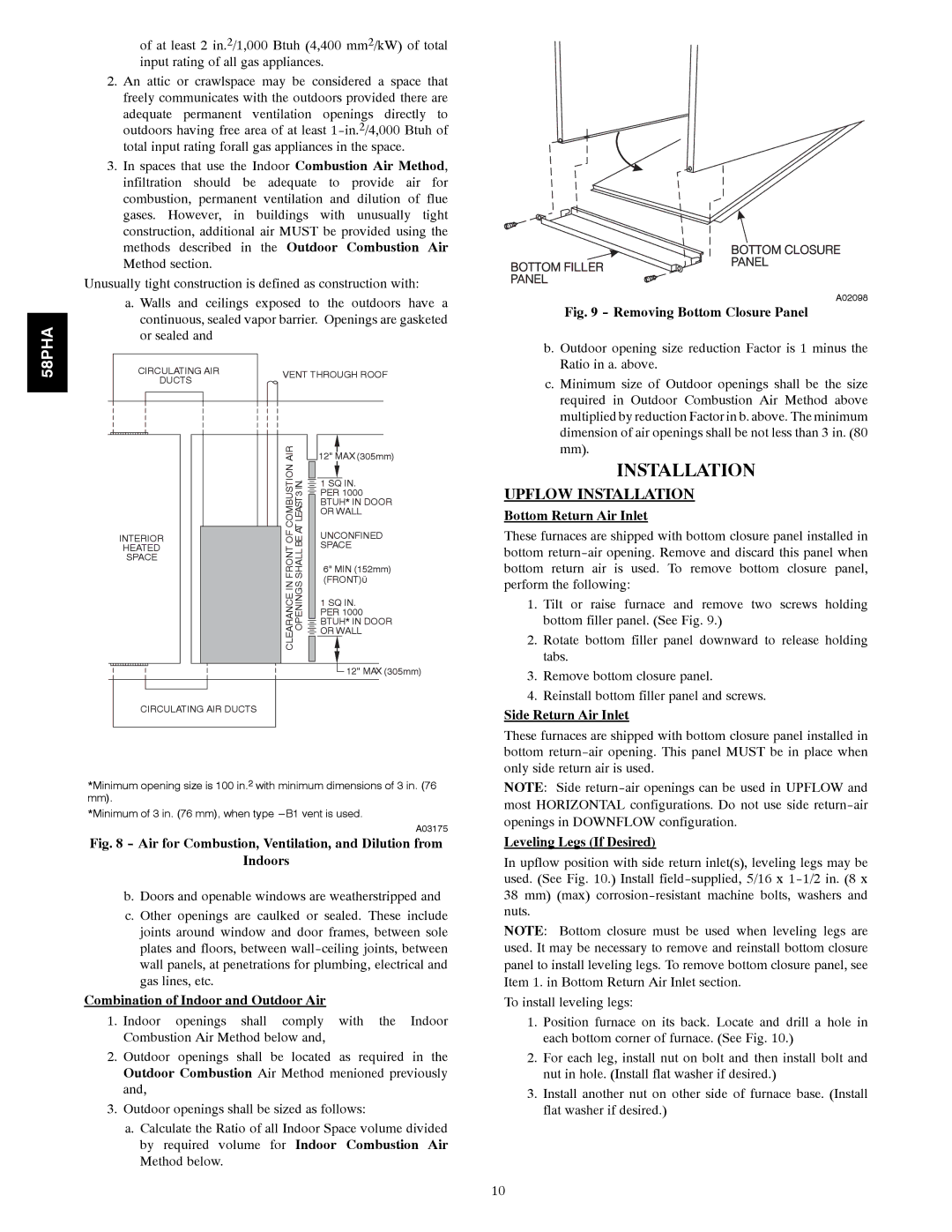
A02098
Fig. 9 - Removing Bottom Closure Panel
b. Outdoor opening size reduction Factor is 1 minus the Ratio in a. above.
c. Minimum size of Outdoor openings shall be the size required in Outdoor Combustion Air Method above multiplied by reduction Factor in b. above. The minimum dimension of air openings shall be not less than 3 in. (80 mm).
INSTALLATION
UPFLOW INSTALLATION
Bottom Return Air Inlet
These furnaces are shipped with bottom closure panel installed in bottom
1.Tilt or raise furnace and remove two screws holding bottom filler panel. (See Fig. 9.)
2.Rotate bottom filler panel downward to release holding tabs.
3.Remove bottom closure panel.
4.Reinstall bottom filler panel and screws.
Side Return Air Inlet
These furnaces are shipped with bottom closure panel installed in bottom
NOTE: Side
Leveling Legs (If Desired)
In upflow position with side return inlet(s), leveling legs may be used. (See Fig. 10.) Install
38mm) (max)
NOTE: Bottom closure must be used when leveling legs are used. It may be necessary to remove and reinstall bottom closure panel to install leveling legs. To remove bottom closure panel, see Item 1. in Bottom Return Air Inlet section.
To install leveling legs:
1.Position furnace on its back. Locate and drill a hole in each bottom corner of furnace. (See Fig. 10.)
2.For each leg, install nut on bolt and then install bolt and nut in hole. (Install flat washer if desired.)
3.Install another nut on other side of furnace base. (Install flat washer if desired.)
10