CN 2110 Temperature Controller
Good Wiring Practices
! ![]()
Separate wire into
•Power leads
•Sensor leads (if power leads must cross sensor leads, they should cross at a 90° angle)
•Output signal lines
Separate sources of electrical
•Motors
•Contacts
•Solenoids
Electrical noise can affect the function of any control system. When driving a contactor coil or other inductive load, an appropriate rated AC snubber circuit is recommended (Omega Part No. CNQUENCHARC).
Connect before power is
Comply with
This instrument is intended for panel mounting and the terminals must be enclosed within a panel. Use National Electric Code (NEC) Class 1 wiring for all terminals except the sensor terminals.
Check wiring
Additional
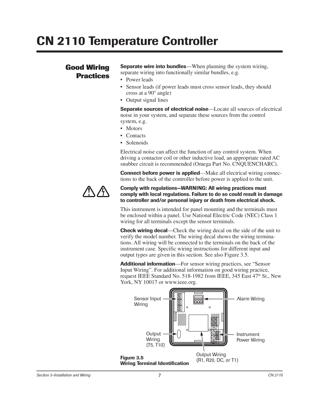
Sensor Input | Alarm Wiring |
Wiring | COM NO NC |
|
Output | Instrument | |
Wiring | Power Wiring | |
(T5, T10) |
| |
Figure 3.5 | Output Wiring | |
(R1, R20, DC, or T1) | ||
Wiring Terminal Identification | ||
|
Section | 7 | CN 2110 |