Omega
Control Output Wiring
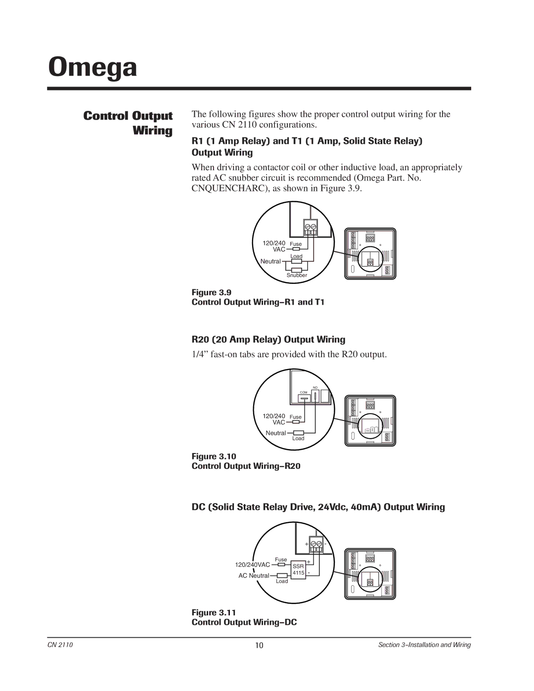
The following figures show the proper control output wiring for the various CN 2110 configurations.
R1 (1 Amp Relay) and T1 (1 Amp, Solid State Relay) Output Wiring
When driving a contactor coil or other inductive load, an appropriately rated AC snubber circuit is recommended (Omega Part. No. CNQUENCHARC), as shown in Figure 3.9.
120/240 | Fuse |
VAC |
|
Neutral | Load |
| |
| Snubber |
Figure 3.9
Control Output
R20 (20 Amp Relay) Output Wiring
1/4”
NO
COM
120/240 Fuse
VAC ![]()
![]()
Neutral
Load
Figure 3.10
Control Output
DC (Solid State Relay Drive, 24Vdc, 40mA) Output Wiring
+ ![]()
![]() -
-
120/240VAC | Fuse |
| + |
| ||||||
|
|
|
|
|
| SSR | - |
| ||
|
|
|
|
|
|
| ||||
AC Neutral |
|
|
|
|
|
|
| 4115 |
| |
|
|
| Load |
|
|
|
|
| ||
|
|
|
|
|
|
|
| |||
Figure 3.11
Control Output
CN 2110 | 10 | Section |