CN 2110 Temperature Controller
Configuration Menus
continued
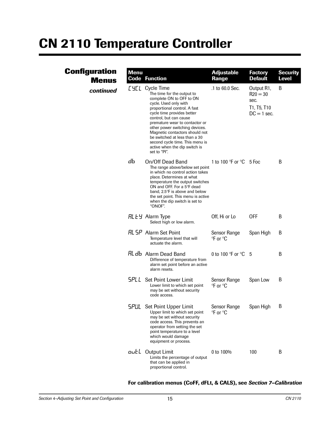
Menu | Adjustable | Factory | Security |
Code Function | Range | Default | Level |
|
|
|
|
Cycle Time | .1 to 60.0 Sec. | Output R1, | B |
The time for the output to |
| R20 = 30 |
|
complete ON to OFF to ON |
| sec. |
|
cycle. Used only with |
| T1, T5, T10 |
|
proportional control. A fast |
|
| |
cycle time provides better |
| DC = 1 sec. |
|
control, but can cause |
|
|
|
premature wear to contactor or |
|
|
|
other power switching devices. |
|
|
|
Magnetic contactors should not |
|
|
|
be switched at less than a 30 |
|
|
|
second cycle time. This menu is |
|
|
|
active when the dip switch is |
|
|
|
set to “PI”. |
|
|
|
On/Off Dead Band | 1 to 100 °F or °C | 5 Foc | B |
The range above/below set point in which no control action takes place. Determines at what temperature the output switches ON and OFF. For a 5°F dead band, 2.5°F is above and below the set point. This menu is active when the dip switch is set to “ONOF”.
Alarm Type | Off, Hi or Lo | OFF | B | |
Select high or low alarm. |
|
|
|
|
Alarm Set Point | Sensor Range | Span High | B | |
Temperature level that will | F or | C |
|
|
° | ° |
|
| |
actuate the alarm. |
|
|
|
|
Alarm Dead Band | 0 to 100 °F or °C | 5 | B | |
Difference of temperature from |
|
|
|
|
alarm set point before an active |
|
|
|
|
alarm resets. |
|
|
|
|
Set Point Lower Limit | Sensor Range | Span Low | B | |
Lower limit to which set point | F or | C |
|
|
° | ° |
|
| |
may be set without security code access.
Set Point Upper Limit
Upper limit to which set point may be set without security code access. This prevents an operator from setting the set point temperature to a level which would damage equipment or process.
Sensor Range | Span High | B |
°F or °C |
|
|
Output Limit | 0 to 100% | 100 | B |
Limits the percentage of output that can be applied in proportional control.
For calibration menus (CoFF, dFLt, & CALS), see Section
Section | 15 | CN 2110 |