CN 2110 Temperature Controller
Sensor Input Wiring
continued
Three-Wire RTD Inputs
IMPORTANT: When making the three-wire RTD input connection, make the resistance of all three extension leadwires equal by using the same gauge and same length of wire for optimum accuracy. A three-wire RTD will generally have two wires of the same color. Connect the same colored wires to the RTDL connections. Connect the alternate colored wire to the RTDH connection.
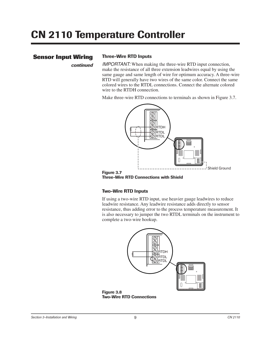
Make three-wire RTD connections to terminals as shown in Figure 3.7.
RTDH
 RTDL
RTDL
RTDL
Shield Ground
Figure 3.7
Three-Wire RTD Connections with Shield
Two-Wire RTD Inputs
If using a two-wire RTD input, use heavier gauge leadwires to reduce leadwire resistance. Any leadwire resistance adds directly to sensor resistance, thus adding error to the process temperature measurement. It is also necessary to jumper the two RTDL terminals on the instrument to complete a two-wire hookup.
RTDH
 RTDL
RTDL
RTDL
Figure 3.8
Two-Wire RTD Connections
Section 3–Installation and Wiring | 9 | CN 2110 |