CN 2110 Temperature Controller
Section 8—Specifications
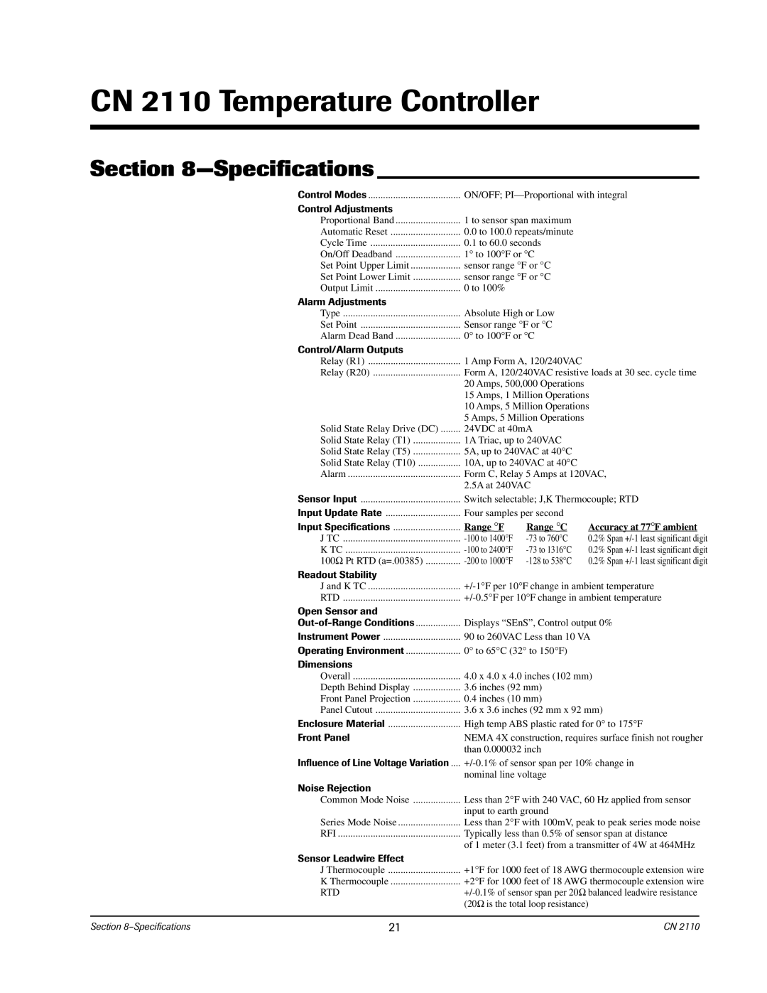
Control Modes | ON/OFF; |
Control Adjustments |
|
Proportional Band | 1 to sensor span maximum |
Automatic Reset | 0.0 to 100.0 repeats/minute |
Cycle Time | 0.1 to 60.0 seconds |
On/Off Deadband | 1° to 100°F or °C |
Set Point Upper Limit | sensor range °F or °C |
Set Point Lower Limit | sensor range °F or °C |
Output Limit | 0 to 100% |
Alarm Adjustments |
|
Type | Absolute High or Low |
Set Point | Sensor range °F or °C |
Alarm Dead Band | 0° to 100°F or °C |
Control/Alarm Outputs |
|
Relay (R1) | 1 Amp Form A, 120/240VAC |
Relay (R20) | Form A, 120/240VAC resistive loads at 30 sec. cycle time |
| 20 Amps, 500,000 Operations |
| 15 Amps, 1 Million Operations |
| 10 Amps, 5 Million Operations |
| 5 Amps, 5 Million Operations |
Solid State Relay Drive (DC) | 24VDC at 40mA |
Solid State Relay (T1) | 1A Triac, up to 240VAC |
Solid State Relay (T5) | 5A, up to 240VAC at 40°C |
Solid State Relay (T10) | 10A, up to 240VAC at 40°C |
Alarm | Form C, Relay 5 Amps at 120VAC, |
| 2.5A at 240VAC |
Sensor Input | Switch selectable; J,K Thermocouple; RTD |
Input Update Rate | Four samples per second |
Input Specifications | Range °F |
J TC | |
K TC | |
100Ω Pt RTD (a=.00385) | |
Readout Stability |
|
Range °C
Accuracy at 77°F ambient 0.2% Span
J and K TC | |
RTD | |
Open Sensor and |
|
Displays “SEnS”, Control output 0% | |
Instrument Power | 90 to 260VAC Less than 10 VA |
Operating Environment | 0° to 65°C (32° to 150°F) |
Dimensions |
|
Overall | 4.0 x 4.0 x 4.0 inches (102 mm) |
Depth Behind Display | 3.6 inches (92 mm) |
Front Panel Projection | 0.4 inches (10 mm) |
Panel Cutout | 3.6 x 3.6 inches (92 mm x 92 mm) |
Enclosure Material | High temp ABS plastic rated for 0° to 175°F |
Front Panel | NEMA 4X construction, requires surface finish not rougher |
| than 0.000032 inch |
Influence of Line Voltage Variation .... | |
| nominal line voltage |
Noise Rejection | Less than 2°F with 240 VAC, 60 Hz applied from sensor |
Common Mode Noise | |
| input to earth ground |
Series Mode Noise | Less than 2°F with 100mV, peak to peak series mode noise |
RFI | Typically less than 0.5% of sensor span at distance |
| of 1 meter (3.1 feet) from a transmitter of 4W at 464MHz |
Sensor Leadwire Effect | +1°F for 1000 feet of 18 AWG thermocouple extension wire |
J Thermocouple | |
K Thermocouple | +2°F for 1000 feet of 18 AWG thermocouple extension wire |
RTD | |
| (20Ω is the total loop resistance) |
Section | 21 | CN 2110 |
