Omega
Sensor Input Wiring Sensor Wiring Notes
For safety and best controller performance,
•Sensor leads (thermocouple and RTD) should not be run in the same conduit as power wiring.
•Twisted pair, shielded wire is recommended for sensor connections.
•False temperature readings can occur if the sensor wire is exposed to electrical noise.
•Ungrounded thermocouples are recommended.
•Thermocouple extension wire, if required, must be the same type as the thermocouple (i.e. if a Type K thermocouple is used, then Type K extension wire must be used.)
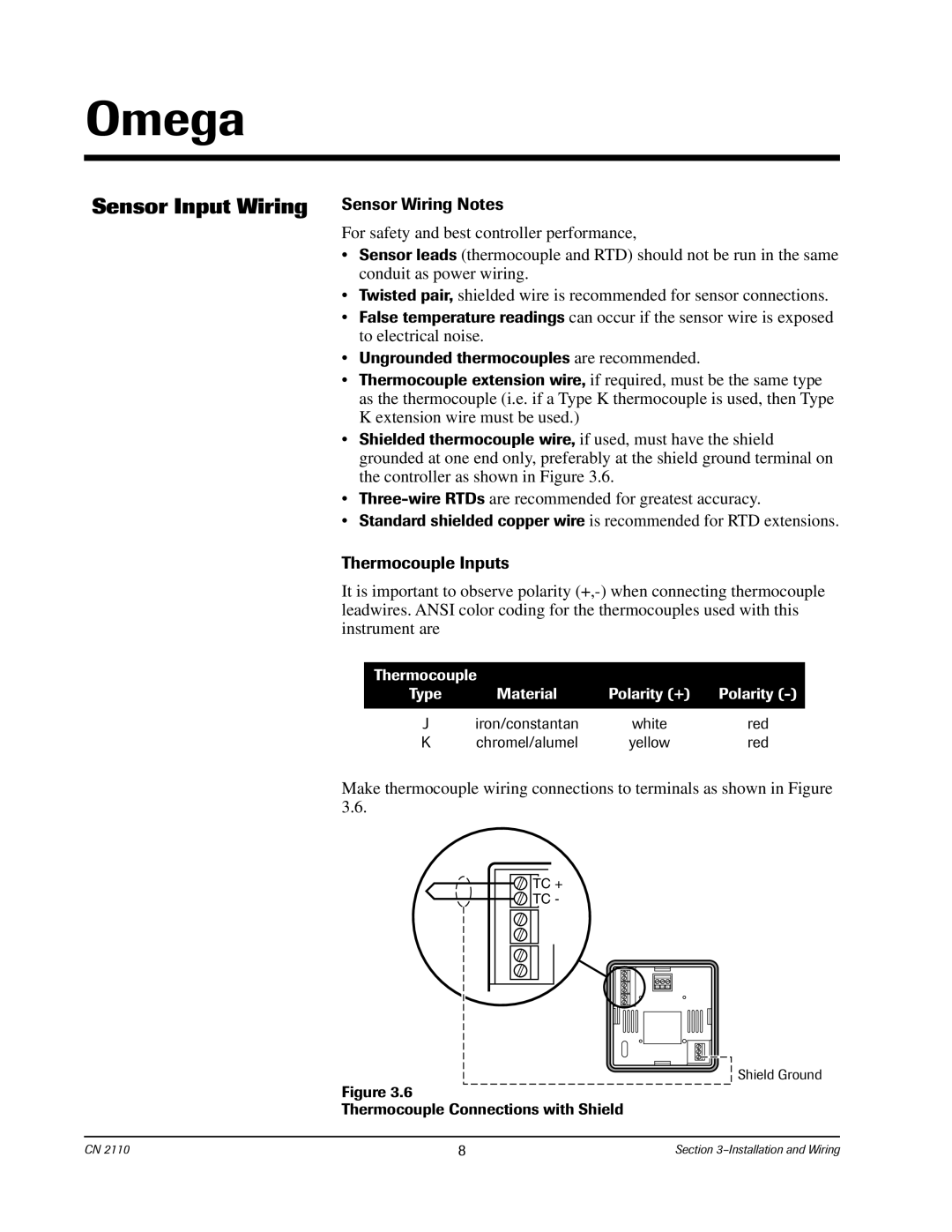
•Shielded thermocouple wire, if used, must have the shield grounded at one end only, preferably at the shield ground terminal on the controller as shown in Figure 3.6.
•
•Standard shielded copper wire is recommended for RTD extensions.
Thermocouple Inputs
It is important to observe polarity
Thermocouple |
|
| |
Type | Material | Polarity (+) | Polarity |
|
|
|
|
J | iron/constantan | white | red |
K | chromel/alumel | yellow | red |
Make thermocouple wiring connections to terminals as shown in Figure 3.6.
TC +
![]() TC -
TC -
Shield Ground
Figure 3.6
Thermocouple Connections with Shield
CN 2110 | 8 | Section |