Wiring Procedure for DC Input
To connect the router to a DC power source, perform the following steps:
Step 1 Remove power from the DC circuit. To ensure that power is removed from the DC circuit, locate the circuit breaker for
|
|
|
| the DC circuit, switch the circuit breaker to the OFF position, and tape the | |
|
|
|
|
|
|
Warning |
| Before performing any of the following procedures, ensure that power is removed from the DC circuit. | |||
|
|
|
|
| Statement 1003 |
|
|
|
|
|
|
|
|
|
|
| |
Tip |
| Secure all power cabling when installing this unit to avoid disturbing | |||
|
|
|
| ||
|
|
|
|
| |
Warning |
| When stranded wiring is required, use approved wiring terminations, such as | |||
|
|
|
|
| upturned lugs. These terminations should be the appropriate size for the wires and should clamp both the |
|
|
|
|
| insulation and conductor. Statement 1002 |
Step 2 |
|
| |||
Strip the wires to the appropriate length for the terminals. The strip length is 3/16 to 1/4 inch (5 to 6 mm) for Amp | |||||
|
|
|
| number 32957 terminals. | |
Step 3 Crimp the terminals onto the DC power input and safety ground wires. | |||||
Step 4 Remove the plastic covers from the terminal block. Save the covers for reinstallation after you finish wiring. | |||||
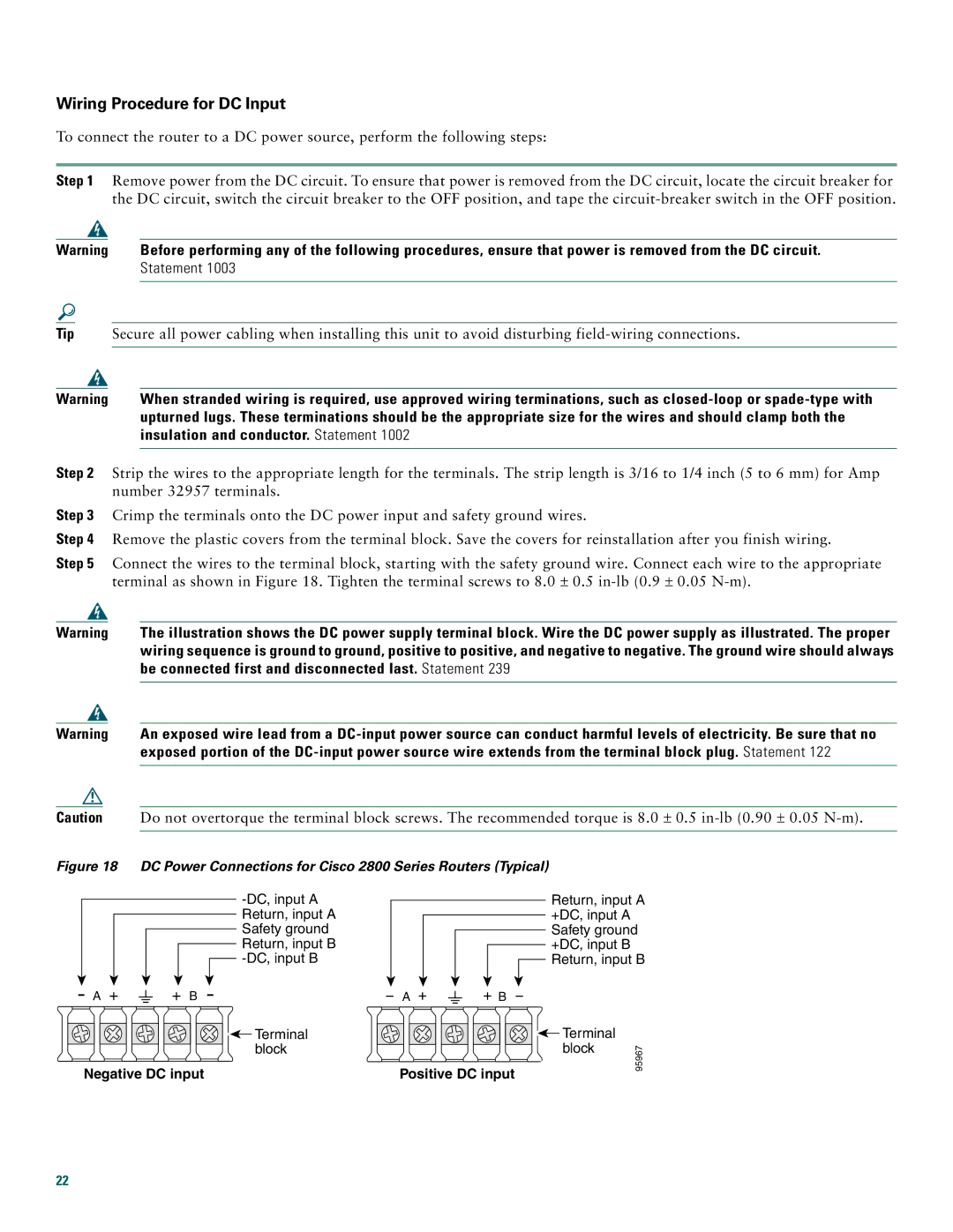
Step 5 | Connect the wires to the terminal block, starting with the safety ground wire. Connect each wire to the appropriate | ||||
|
|
|
| terminal as shown in Figure 18. Tighten the terminal screws to 8.0 ± 0.5 | |
|
|
|
|
| |
Warning |
| The illustration shows the DC power supply terminal block. Wire the DC power supply as illustrated. The proper | |||
|
|
|
|
| wiring sequence is ground to ground, positive to positive, and negative to negative. The ground wire should always |
|
|
|
|
| be connected first and disconnected last. Statement 239 |
|
|
|
| ||
|
|
|
|
| |
Warning |
| An exposed wire lead from a | |||
|
|
|
|
| exposed portion of the |
|
|
|
|
| |
|
|
|
|
| |
Caution |
|
| Do not overtorque the terminal block screws. The recommended torque is 8.0 ± 0.5 | ||
|
|
|
|
|
|
Figure 18 DC Power Connections for Cisco 2800 Series Routers (Typical)
| |
| Return, input A |
| Safety ground |
| Return, input B |
| |
A + | + B |
A + | + B |
Return, input A +DC, input A Safety ground +DC, input B Return, input B
![]()
![]() Terminal block
Terminal block
Negative DC input
![]() Terminal block
Terminal block
Positive DC input
95967
22