Chapter 3 Initial Configuration
About CPU Switch Module Redundancy
Table
State | Description |
|
|
Active | Processor card is currently providing clock signals and control for all system |
| cards. The active CPU switch module responds to the configured |
| management IP address. |
|
|
Standby | Processor card is partially booted in |
| when the active CPU switch module fails, when it is rebooted or removed, |
| or when a manual switchover is requested. |
|
|
Nonparticipant | Processor card is in ROMMON mode, or is in the process of booting, or has |
| not yet reached the |
| the force option is used. |
|
|
Not plugged in | Processor card slot is empty. |
|
|
Error | Processor card is present but either the interprocess arbitration interface is |
| not functioning or the CPU switch module is not fully seated in the chassis |
| slot. |
|
|
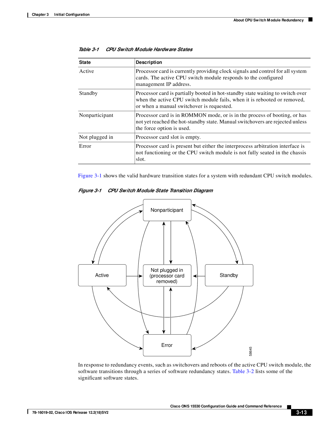
Figure 3-1 shows the valid hardware transition states for a system with redundant CPU switch modules.
Figure 3-1 CPU Switch Module State Transition Diagram
Nonparticipant
Active | Not plugged in | Standby |
(processor card | ||
| removed) |
|
Error
58645
In response to redundancy events, such as switchovers and reboots of the active CPU switch module, the software transitions through a series of software redundancy states. Table
|
| Cisco ONS 15530 Configuration Guide and Command Reference |
|
| ||
|
|
| ||||
|
|
|
| |||
|
|
|
| |||