Chapter 3 Initial Configuration
Configuring CPU Switch Module Redundancy
Examples
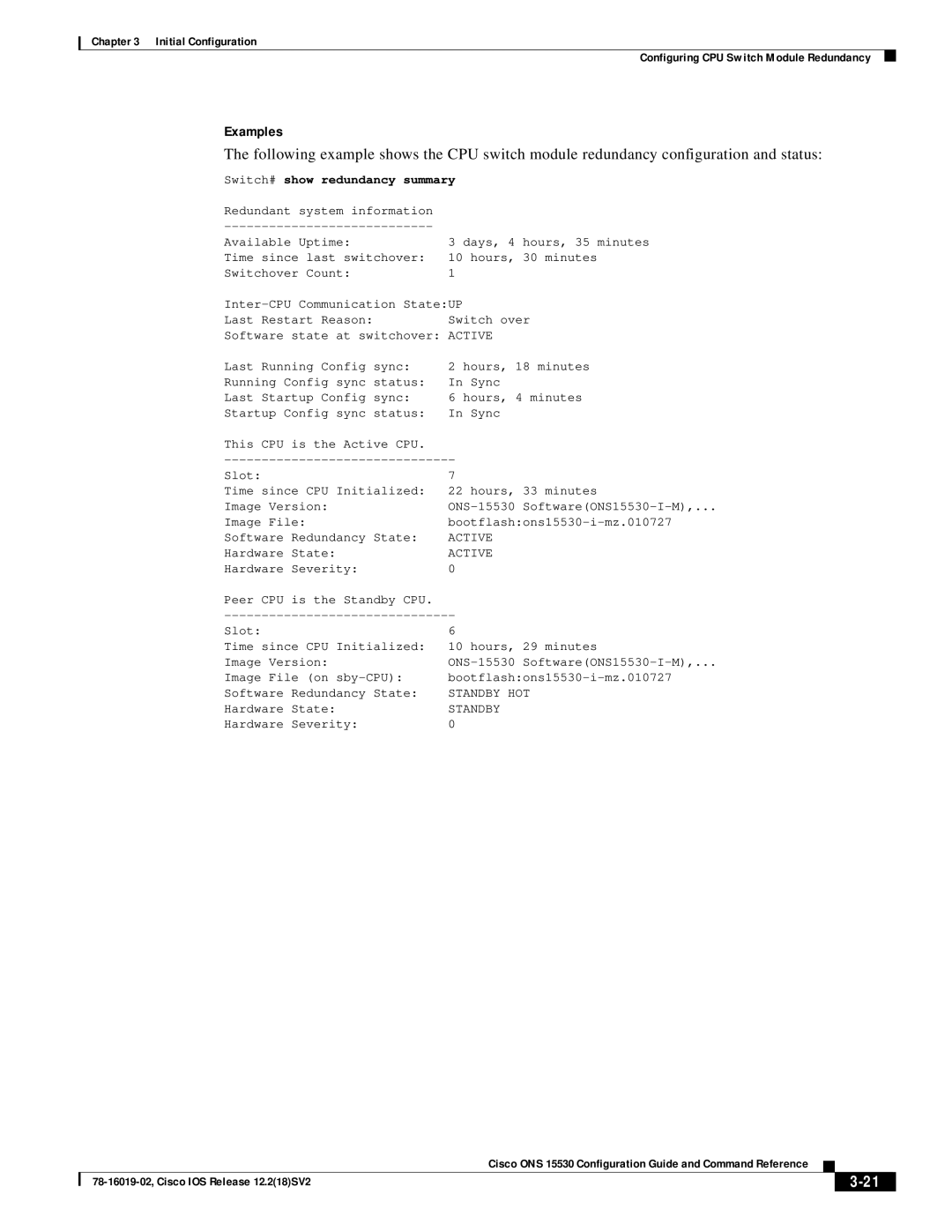
The following example shows the CPU switch module redundancy configuration and status:
Switch# show redundancy summary
Redundant system information |
|
| |
Available Uptime: | 3 days, 4 hours, 35 minutes |
Time since last switchover: | 10 hours, 30 minutes |
Switchover Count: | 1 |
Last Restart Reason: | Switch over |
Software state at switchover: | ACTIVE |
Last Running Config sync: | 2 hours, 18 minutes |
Running Config sync status: | In Sync |
Last Startup Config sync: | 6 hours, 4 minutes |
Startup Config sync status: | In Sync |
This CPU | is the Active CPU. |
|
Slot: |
| 7 |
Time since CPU Initialized: | 22 hours, 33 minutes | |
Image Version: | ||
Image File: | ||
Software | Redundancy State: | ACTIVE |
Hardware | State: | ACTIVE |
Hardware | Severity: | 0 |
Peer CPU | is the Standby CPU. |
|
Slot: |
| 6 |
Time since CPU Initialized: | 10 hours, 29 minutes | |
Image Version: | ||
Image File (on | ||
Software | Redundancy State: | STANDBY HOT |
Hardware | State: | STANDBY |
Hardware | Severity: | 0 |
|
| Cisco ONS 15530 Configuration Guide and Command Reference |
|
| ||
|
|
| ||||
|
|
|
| |||
|
|
|
| |||
