Connecting Cables to the Router
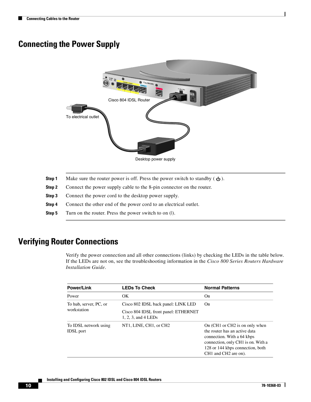
Connecting the Power Supply
TO HUB
TO PC
ETHER | NET 10 | BASE T | Cisco | 804 | IDSL |
|
|
| |||
|
|
| CO |
| |
|
|
|
|
| |
|
|
| NSOLE |
|
|
1 |
|
|
|
|
|
2 |
| 3 |
|
|
|
|
| 4 |
|
| |
|
|
|
|
|
Cisco 804 IDSL Router
IDSL
2
+5,
To electrical outlet
Desktop power supply
Step 1 Make sure the router power is off. Press the power switch to standby ( ![]() ).
).
Step 2 Connect the power supply cable to the
Step 3 Connect the power cord to the desktop power supply.
Step 4 Connect the other end of the power cord to an electrical outlet.
Step 5 Turn on the router. Press the power switch to on ().
Verifying Router Connections
Verify the power connection and all other connections (links) by checking the LEDs in the table below. If the LEDs are not on, see the troubleshooting information in the Cisco 800 Series Routers Hardware Installation Guide.
|
|
|
| Power/Link | LEDs To Check | Normal Patterns |
| |
|
|
|
| Power | OK | On | ||
|
|
|
|
|
|
|
| |
|
|
|
| To hub, server, PC, or | Cisco 802 IDSL back panel: LINK LED | On | ||
|
|
|
| workstation | Cisco 804 IDSL front panel: ETHERNET |
|
|
|
|
|
|
|
|
|
|
| |
|
|
|
|
| 1, 2, 3, and 4 LEDs |
|
|
|
|
|
|
|
|
|
|
| |
|
|
|
| To IDSL network using | NT1, LINE, CH1, or CH2 | On (CH1 or CH2 is on only when | ||
|
|
|
| IDSL port |
| the router has an active data | ||
|
|
|
|
|
| connection. With a 64 kbps | ||
|
|
|
|
|
| connection, only CH1 is on. With a | ||
|
|
|
|
|
| 128 or 144 kbps connection, both | ||
|
|
|
|
|
| CH1 and CH2 are on). | ||
|
|
|
|
|
|
|
| |
|
|
| Installing and Configuring Cisco 802 IDSL and Cisco 804 IDSL Routers |
|
|
| ||
|
|
|
|
|
| |||
|
|
|
|
|
|
|
|
|
| 10 |
|
|
|
|
| ||
|
|
|
|
|
| |||