Checking LEDs
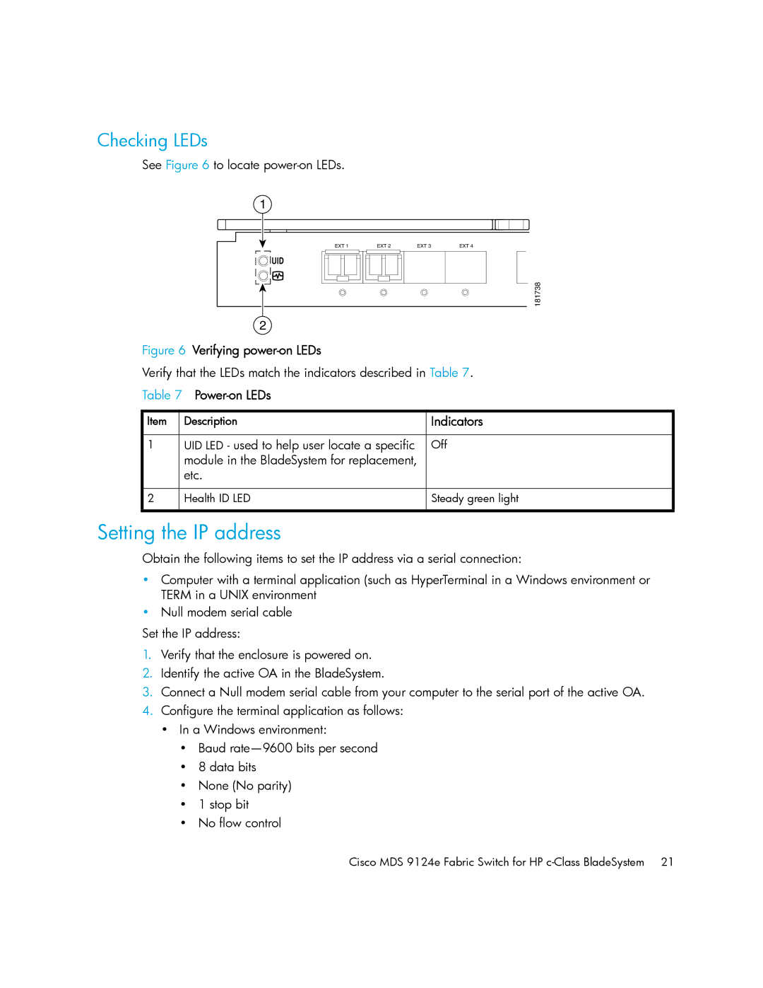
See Figure 6 to locate
1 |
|
|
|
EXT 1 | EXT 2 | EXT 3 | EXT 4 |
! |
|
|
|
: |
|
| 181738 |
|
|
| |
2 |
|
|
|
Figure 6 Verifying power-on LEDs
Verify that the LEDs match the indicators described in Table 7.
Table 7 Power-on LEDs
Item | Description | Indicators |
|
|
|
1 | UID LED - used to help user locate a specific | Off |
| module in the BladeSystem for replacement, |
|
| etc. |
|
|
|
|
2 | Health ID LED | Steady green light |
|
|
|
Setting the IP address
Obtain the following items to set the IP address via a serial connection:
•Computer with a terminal application (such as HyperTerminal in a Windows environment or TERM in a UNIX environment
•Null modem serial cable
Set the IP address:
1.Verify that the enclosure is powered on.
2.Identify the active OA in the BladeSystem.
3.Connect a Null modem serial cable from your computer to the serial port of the active OA.
4.Configure the terminal application as follows:
•In a Windows environment:
•Baud
•8 data bits
•None (No parity)
•1 stop bit
•No flow control
Cisco MDS 9124e Fabric Switch for HP