Interpreting LED activity
You can monitor switch activity and status by checking the switch LEDs.
There are three possible LED states: no light, a steady light, or a flashing light. The steady lights and flashing lights can be green or amber.
The LEDs flash any of these colors during boot, POST, or other diagnostic tests. This is normal and does not indicate a problem unless the LEDs do not indicate a healthy state after all boot processes and diagnostic tests are complete. A healthy state is indicated by a steady green light. See Table 11 for details about LED activity.
LED indicators
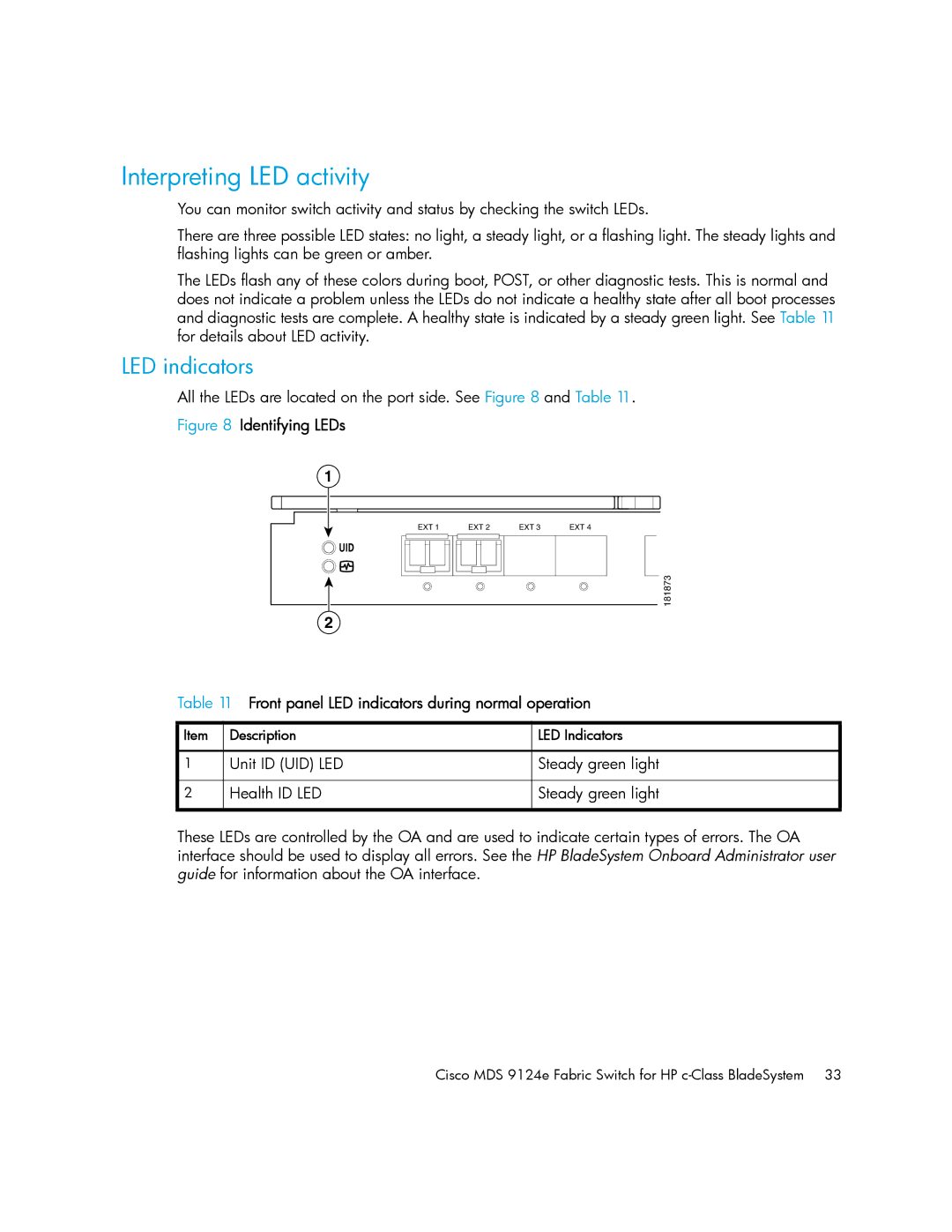
All the LEDs are located on the port side. See Figure 8 and Table 11.
Figure 8 Identifying LEDs
1
EXT 1 | EXT 2 | EXT 3 | EXT 4 |
! |
|
|
|
|
|
| 181873 |
2 |
|
|
|
Table 11 Front panel LED indicators during normal operation
Item | Description | LED Indicators |
|
|
|
1 | Unit ID (UID) LED | Steady green light |
|
|
|
2 | Health ID LED | Steady green light |
|
|
|
These LEDs are controlled by the OA and are used to indicate certain types of errors. The OA interface should be used to display all errors. See the HP BladeSystem Onboard Administrator user guide for information about the OA interface.
Cisco MDS 9124e Fabric Switch for HP