Port side of the Switch
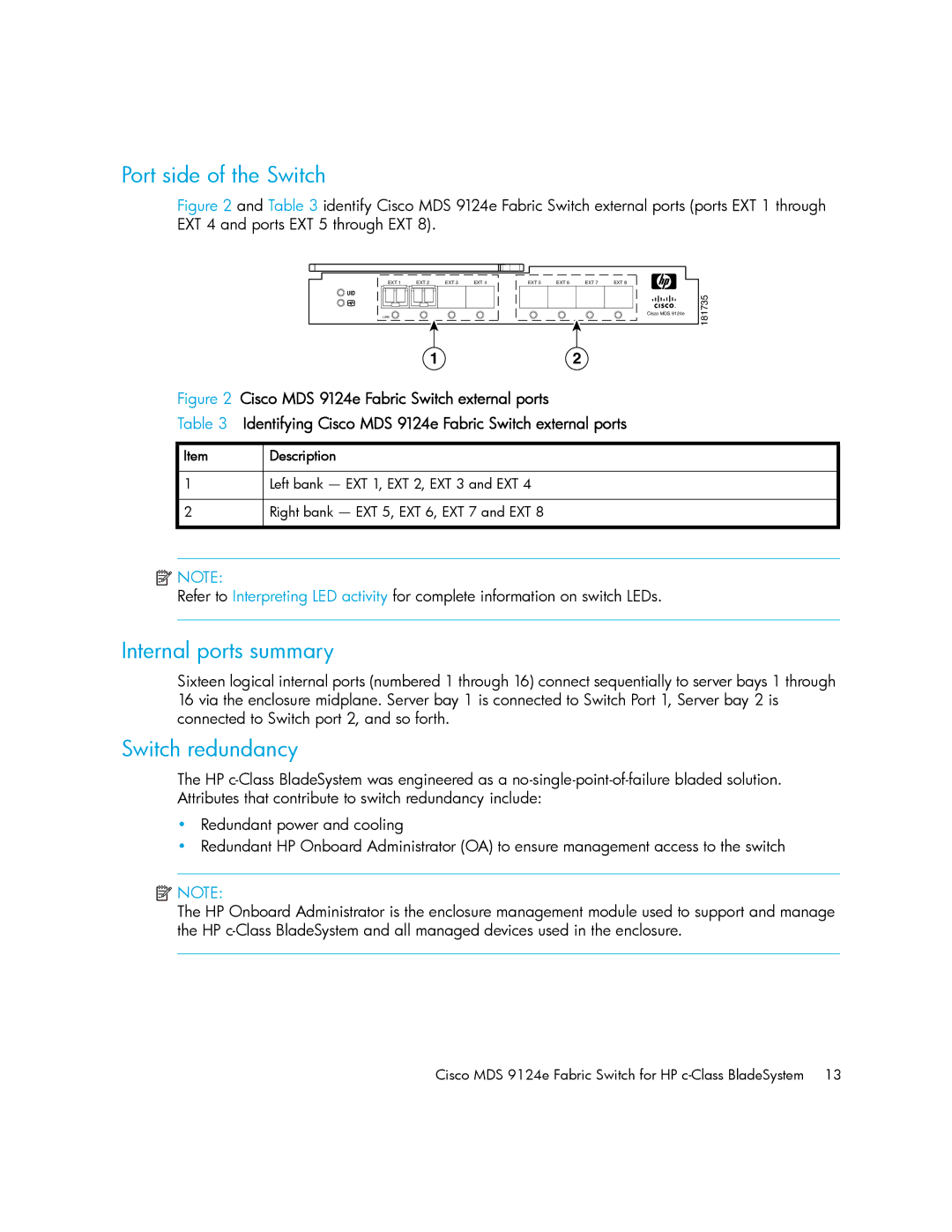
Figure 2 and Table 3 identify Cisco MDS 9124e Fabric Switch external ports (ports EXT 1 through EXT 4 and ports EXT 5 through EXT 8).
EXT 1 | EXT 2 | EXT 3 | EXT 4 | EXT 5 | EXT 6 | EXT 7 | EXT 8 |
!
Cisco MDS 9124e
LiNK
12
Figure 2 Cisco MDS 9124e Fabric Switch external ports
Table 3 Identifying Cisco MDS 9124e Fabric Switch external ports
Item | Description |
1Left bank — EXT 1, EXT 2, EXT 3 and EXT 4
2Right bank — EXT 5, EXT 6, EXT 7 and EXT 8
181735
![]() NOTE:
NOTE:
Refer to Interpreting LED activity for complete information on switch LEDs.
Internal ports summary
Sixteen logical internal ports (numbered 1 through 16) connect sequentially to server bays 1 through 16 via the enclosure midplane. Server bay 1 is connected to Switch Port 1, Server bay 2 is connected to Switch port 2, and so forth.
Switch redundancy
The HP
•Redundant power and cooling
•Redundant HP Onboard Administrator (OA) to ensure management access to the switch
![]() NOTE:
NOTE:
The HP Onboard Administrator is the enclosure management module used to support and manage the HP
Cisco MDS 9124e Fabric Switch for HP