Spec Sheet
SAN JOSE, CA REV C.18 December 17
Step Verify Server SKU
Step
Contents
Page
Overview
Chassis Front View
Shows the Cisco UCS C220 M3 High-Density SFF Rack Server
Shows the external features of the rear panel
Chassis Rear View
CPU
Capabilities and Features Capability/Feature Description
Chassis One rack unit 1RU chassis
NIC
Capability/Feature Description
Acpi
Configuring the Server
Verify the product ID PID of the server as shown in Table
Verify Server SKU
Cards, with 1 rail kit
Product ID PID Freq Size Cores
Select CPUs
DDR3 Dimm
QPI
Number GHz Support MHz1 Intel Xeon E5-26002
Select two identical CPUs from any one of the rows of on
Approved Configurations CPU configurations
Select any one CPU listed in Table
Caveats
Select Memory
C220 M3 SFF Memory Organization
Dimm Options
Select DIMMs and Memory Mirroring
Dimm
Memory Mirroring Option
CPU configuration with memory mirroring
A1, B1 A1,B1 C1,D1 A1,B1, C1 A2, B2, C2 A2,B2 C2,D2
A1, B1 E1, F1 A1,B1 C1,D1
Dimm Memory Speeds
DPC
Configuring the Server
Select RAID Configuration
Product ID PID PID Description RAID Controllers
Select RAID Options
Available Embedded RAID Options
UCSC-RAID-ROM5
UCSC-RAID-11-C220
UCSC-RAID-MZ-220
Available PCIe RAID Controller Options
RAID Configuration Options not available for embedded RAID
Super Capacitor Option
Approved Configurations
RAID RAID1
RAID4
Caveats
HDDs
Select Drives
SSDs
You can mix Sata and SAS drives
Network Interface Cards NICs
Select PCIe Option Cards
Host Bus Adapters HBAs
UCS Storage Accelerators
Approved Configurations No PCIe RAID controller
One PCIe RAID controller
Configuring the Server
Available Twinax Cables Product ID PID PID Description
Order Optional Network Card Accessories
Choose Optional Twinax Cables
Choose Optional SFP Modules
Caveats
Cisco VIC 1225 Dual Port 10Gb SFP+ CNA
Preinstalled do not change SFP
Broadcom 57712 Dual Port 10Gb SFP+ w/TOE iSCSI
Cisco VIC 1225T Dual Port 10GBaseT CNA
Network Card Connections
UCSC-PSU-450W
Order Power Supply
Power Supply PIDs
UCSC-PSU-650W
CAB-N5K6A-NA
Available Power Cords Product ID PID PID Description Images
R2XX-DMYMPWRCORD
CAB-C13-CBN
CAB-9K10A-AU
CAB-9K10A-EU
Available Power Cords Product ID PID PID Description
UCSC-CMA1
Order Optional Reversible Cable Management ARM
Cable Management Arm
Cable Management Arm for C220 rack servers
Trusted Platform Module Product ID PID PID Description
Order a Trusted Platform Module Optional
UCSX-TPM1-001 Trusted Platform Module
Second Secure Digital SD Card blank
Order Cisco Flexible Flash SD Card Module Optional
Secure Digital SD Card preloaded with software
UCS-SD-16G
USB 2.0 Drive
See on page 57 for the location of the USB connector
Order Optional USB 2.0 Drive
UCS-USBFLSH-S-4GB
Select Operating System and VALUE-ADDED Software
Suse
Nexus 1000V for Hyper-V and vSphere
BMC
UCS Director
Configuring the Server
Select Operating System Media KIT
OS Media Product ID PID PID Description
SMARTnet for UCS
Unified Computing Warranty, No Contract
Cisco SMARTnet for UCS Service
Product ID PID On Site? Description
CON-UCW5-C220M3SF
CON-UCW7-C220M3SF
UCS HW 24X7X4OS UCS C220 M3 SFF
UC Plus 8X5XNBDOS UCS C220 M3 SFF
Unified Computing Combined Support Service
Partner Support Service for UCS
Service Product ID PID Level Description Site?
GSP
UCSD7
UCS DR UCSD7
UCWD5
UCWD7
CON-UCWD7-C220M3SF
CON-UCWD5-C220M3SF
Racks and Rack Options
Product ID PID PID Description RP208-30-2P-U-2 Zero RU PDU
PDU Options
For more information about the PDU, see PDUs,
Supplemental Material
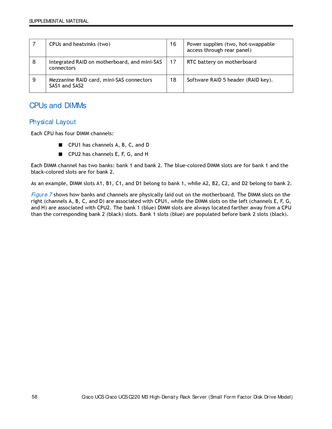
CPUs and DIMMs
Physical Layout
CPU1
DPC
Memory Population Rules
DPC or 2 DPC
DIMMs per Channel DPC
Dimm Population Order
Populate the DIMMs for a CPU according to Table
Recommended Memory Configuration
CPU
Supported Dimm Configurations Total DIMMs
Supported Dimm Populations
Total
Low-Voltage Dimm Considerations
CPU Configurations Select one of the following
Available RAID configurations are shown in this section
RAID Details
RAID Option ROM Oprom Settings
Example Bios Screen for Oprom
Serial Port Female RJ-45 Connector Pinout
Serial Port Details
Upgrade and Servicing-Related Parts
Drive Blanking Panels
Motherboard Lithium Battery
CPU Removal and Installation pick n place Tool Set
Adding an Additional CPU with CPU heat sink
Air Baffle Replacement Kit
CPU Heat Sink Cleaning Kit
Racks
Cisco R42610 Rack
PDUs
Zero Rack Unit PDU PID = RP208-30-2P-U-2
KVM cable for B-Series Blade Server console port
KVM Cable Product ID PID PID Description
N20-BKVM
KVM Cable
Motherboard USB and SD Ports, and RAID Card Backup Location
Power Specifications
Dimensions and Weight
UCS C220 M3 Dimensions and Weight Parameter Value
Technical Specifications
Input
Class RSP1
Output
Environmental Specifications
UCS C220 M3 Environmental Specifications Parameter Minimum
EN300386
Compliance Requirements
CISPR24
KN24