Chapter 2 Getting Started
Installing the Cisco Video Surveillance 2621 IP Dome
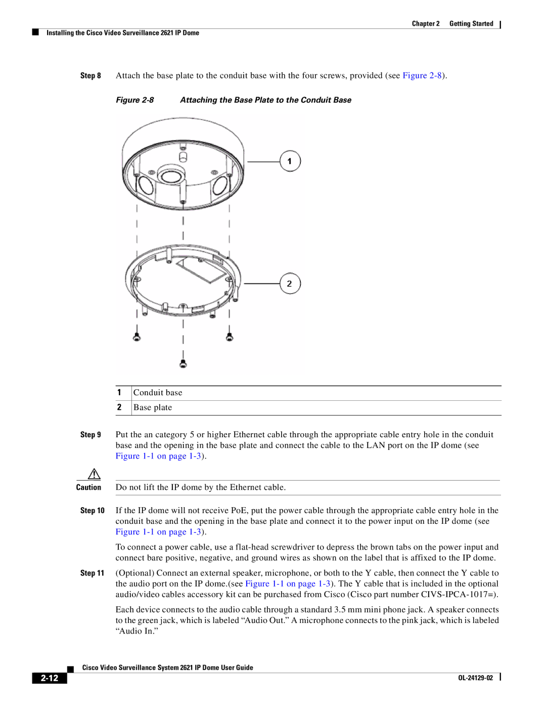
Step 8 Attach the base plate to the conduit base with the four screws, provided (see Figure
Figure 2-8 Attaching the Base Plate to the Conduit Base
1
2
Conduit base
Base plate
Step 9 Put the an category 5 or higher Ethernet cable through the appropriate cable entry hole in the conduit base and the opening in the base plate and connect the cable to the LAN port on the IP dome (see Figure
Caution Do not lift the IP dome by the Ethernet cable.
Step 10 If the IP dome will not receive PoE, put the power cable through the appropriate cable entry hole in the conduit base and the opening in the base plate and connect it to the power input on the IP dome (see Figure
To connect a power cable, use a
Step 11 (Optional) Connect an external speaker, microphone, or both to the Y cable, then connect the Y cable to the audio port on the IP dome.(see Figure
Each device connects to the audio cable through a standard 3.5 mm mini phone jack. A speaker connects to the green jack, which is labeled “Audio Out.” A microphone connects to the pink jack, which is labeled “Audio In.”
| Cisco Video Surveillance System 2621 IP Dome User Guide |
