Chapter 2 Getting Started
Installing the Cisco Video Surveillance 2621 IP Dome
•Mounting with a Conduit Base, page
•Mounting to a Ceiling Tile, page
•Mounting on a Solid Surface, page
Preparing for Installation
Before you install the IP dome, follow these guidelines:
•Carefully unpack the IP dome and its components.
•Run an category 5 or higher network cable cabling to the mounting location.
•If the IP dome will not be powered from PoE, run a power cable from a 12 VDC or 24 VAC power adapter to the mounting location
Use a cable gauge that is appropriate for the distance from the IP dome to the power supply (consult a qualified electrician for more information). The terminal connectors on the IP dome support gauges from 14 AWG to 24 AWG. At the end of the wire that attaches to the IP dome, strip enough cable housing to allow each wire to be stripped to 1/4 inch (6.25 mm).
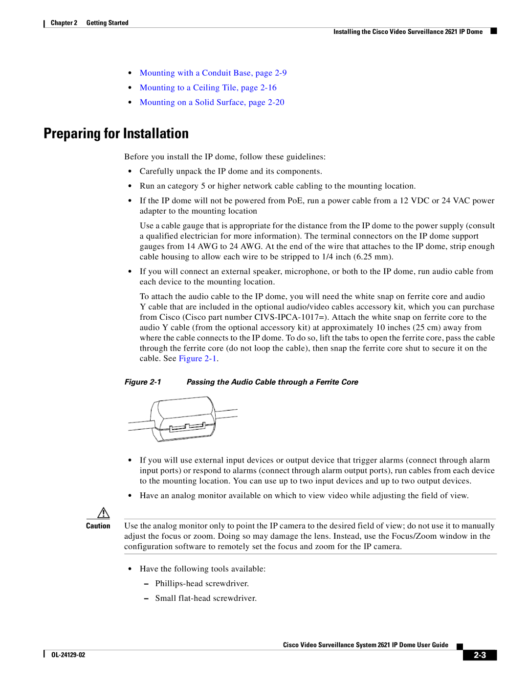
•If you will connect an external speaker, microphone, or both to the IP dome, run audio cable from each device to the mounting location.
To attach the audio cable to the IP dome, you will need the white snap on ferrite core and audio Y cable that are included in the optional audio/video cables accessory kit, which you can purchase from Cisco (Cisco part number
Figure 2-1 Passing the Audio Cable through a Ferrite Core
•If you will use external input devices or output device that trigger alarms (connect through alarm input ports) or respond to alarms (connect through alarm output ports), run cables from each device to the mounting location. You can use up to two input devices and up to two output devices.
•Have an analog monitor available on which to view video while adjusting the field of view.
Caution Use the analog monitor only to point the IP camera to the desired field of view; do not use it to manually adjust the focus or zoom. Doing so may damage the lens. Instead, use the Focus/Zoom window in the configuration software to remotely set the focus and zoom for the IP camera.
•Have the following tools available:
–
–Small
Cisco Video Surveillance System 2621 IP Dome User Guide
|
| ||
|
|