Chapter 3 Configuring and Managing the IP Camera
Applications Windows
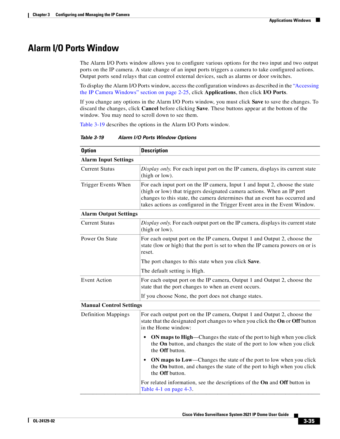
Alarm I/O Ports Window
The Alarm I/O Ports window allows you to configure various options for the two input and two output ports on the IP camera. A state change of an input ports triggers a camera to take configured actions. Output ports send relays that can control external devices, such as alarms or door switches.
To display the Alarm I/O Ports window, access the configuration windows as described in the “Accessing the IP Camera Windows” section on page
If you change any options in the Alarm I/O Ports window, you must click Save to save the changes. To discard the changes, click Cancel before clicking Save. These buttons appear at the bottom of the window. You may need to scroll down to see them.
Table
Table
Option | Description |
|
|
Alarm Input Settings |
|
|
|
Current Status | Display only. For each input port on the IP camera, displays its current state |
| (high or low). |
|
|
Trigger Events When | For each input port on the IP camera, Input 1 and Input 2, choose the state |
| (high or low) that triggers designated camera actions. When an IP port |
| changes to this state, the camera determines that an event has occurred and |
| takes actions as configured in the Trigger Event area in the Event Window. |
|
|
Alarm Output Settings |
|
|
|
Current Status | Display only. For each output port on the IP camera, displays its current state |
| (high or low). |
|
|
Power On State | For each output port on the IP camera, Output 1 and Output 2, choose the |
| state (low or high) that the port is set to when the IP camera powers on or is |
| reset. |
| The port changes to this state when you click Save. |
| The default setting is High. |
|
|
Event Action | For each output port on the IP camera, Output 1 and Output 2, choose the |
| state that the port changes to when an event occurs. |
| If you choose None, the port does not change states. |
|
|
Manual Control Settings
Definition Mappings
For each output port on the IP camera, Output 1 and Output 2, choose the state that the designated port changes to when you click the On or Off button in the Home window:
•ON maps to
•ON maps to
For related information, see the descriptions of the On and Off button in Table
|
| Cisco Video Surveillance System 2621 IP Dome User Guide |
|
| |
|
|
| |||
|
|
|
| ||
|
|
|
| ||