Objectives
Changes to This Document
Release No Revision Date Change Summary
Viii
Section Title Description
Organization
Related Documentation
Troubleshooting
Preface
Xii
Product Overview
Product Overview
76-ES+XT-2TG3CXL 76-ES+XT-2TG3CXL=
FRU Product ID
Supported Platform
Supported Platforms
DFC 3C
Modular Optics Compatibility
XFP Modules see -5 on
Line Cards Supported Modules
Cisco 7600 Series ES+ line cards
Power Management
Router# show power
Router#show power
Overview Cisco 7600 Series Ethernet Services Plus Line Cards
Minimum Cisco
Product Numbers
SFPs or XFPs IOS Release
Checking Hardware and Software Compatibility
Router# show module
Cisco 7600 ES+ Line Card Slot, Bay, and Port Locations
Type Speed Description
Cisco 7600 ES+ 2TG3C, 7600 ES+ 2TG3CXL Line Card Processors
Description Specifications
Cisco 7600 ES+ 2TG3C, 7600 ES+ 2TG3CXL Line Card LEDs
LED Label Color State Meaning
XFP
Line Card Memory Options
XFP
Cisco 7600 ES+ 4TG3C, 7600 ES+ 4TG3CXL Line Card Overview
Connectors and Cabling
Cisco 7600 ES+ 4TG3C, 7600 ES+ 4TG3CXL Line Card LEDs
Cisco 7600 ES+ 4TG3C, 7600 ES+ 4TG3CXL Line Card Processors
Cisco 7600 ES+ 4TG3C, 7600 ES+ 4TG3CXL Supported XFP Modules
XFP-10GLR-OC192SR-L
Connectors and Cabling
Cisco 7600 ES+ 20G3C, 7600 ES+ 20G3CXL Line Card LEDs
Cisco 7600 ES+ 20G3C, 7600 ES+ 20G3CXL Line Card Processors
13provides LED descriptions
SFP Modules Description
Cisco 7600 ES+ 20G3C, 7600 ES+ 20G3CXL Supported SFP Modules
SFP Modules
11 SFP Optics Module
Cisco 7600 ES+ 40G3C, 7600 ES+ 40G3CXL Line Card LEDs
Cisco 7600 ES+ 40G3C, 7600 ES+ 40G3CXL Line Card Processors
18provides LED descriptions
Cisco 7600 ES+ 40G3C, 7600 ES+ 40G3CXL Supported SFP Modules
SFP Modules
15 SFP Optics Module
Cisco 76-ES+XT-2TG3C, 76-ES+XT-2TG3CXL Line Card LEDs
Cisco 76-ES+XT-2TG3C, 76-ES+XT-2TG3CXL Line Card Processors
23provides LED descriptions
Cisco 76-ES+XT-2TG3C, 76-ES+XT-2TG3CXL Supported XFP Modules
XFP
Cisco 76-ES+XT-4TG3C, 76-ES+XT-4TG3CXL Line Card Overview
Cisco 76-ES+XT-4TG3C, 76-ES+XT-4TG3CXL Line Card LEDs
Cisco 76-ES+XT-4TG3C, 76-ES+XT-4TG3CXL Line Card Processors
28provides LED descriptions
Cisco 76-ES+XT-4TG3C, 76-ES+XT-4TG3CXL Supported SFP Modules
Connectors and Cabling
Cisco 76-ES+T-20G Line Card Processors
Cisco 76-ES+T-20G Line Card Overview
Cisco 76-ES+T-20G Line Card LEDs
Cisco 76-ES+T-20G Physical Specifications
Cisco 76-ES+T-20G Supported SFP Modules
Cisco 76-ES+T-20G Line Card Memory Options
36 Cisco 76-ES+T-20G Supported SFP Modules
26 SFP Optics Module
Cisco 76-ES+T-40G Line Card Overview
Cisco 76-ES+T-40G Line Card Processors
Cisco 76-ES+T-40G Line Card LEDs
Line Card
Cisco 76-ES+T-40G Physical Specifications
Cisco 76-ES+T-40G Line Card Memory Options
Cisco 76-ES+T-40G Supported SFP Modules
Cisco 76-ES+T-40G Supported SFP Modules
41 Cisco 76-ES+T-40G Supported SFP Modules
Cisco 76-ES+T-2TG Line Card Processors,
Cisco 76-ES+T-2TG Line Card Overview
Cisco 76-ES+T-2TG Line Card LEDs
Cisco 76-ES+T-2TG Line Card Processors
Cisco 76-ES+T-2TG Physical Specifications
Cisco 76-ES+T-2TG Line Card Memory Options
Cisco 76-ES+T-2TG Supported XFP Modules
XFP
33 Duplex LC-Type Cable and Connector
Cisco 76-ES+T-4TG Line Card Overview
Cisco 76-ES+T-4TG Line Card Processors
Cisco 76-ES+T-4TG Line Card LEDs
Color State Meaning
Cisco 76-ES+T-4TG Physical Specifications
Cisco 76-ES+T-4TG Line Card Memory Options
Cisco 76-ES+T-4TG Supported XFP Modules
XFP-10GLR-OC192SR-L
Connectors and Cabling
36 Duplex LC-Type Cable and Connector
Cisco 76-ES+XC-20G3C, 76-ES+XC-20G3CXL Line Card LEDs
Cisco 76-ES+XC-20G3C, 76-ES+XC-20G3CXL Line Card Processors
53provides LED descriptions
Cisco 76-ES+XC-20G3C, 76-ES+XC-20G3CXL Supported SFP Modules
SFP Modules
Cisco 76-ES+XC-20G3C, 76-ES+XC-20G3CXL Supported XFP Modules
XFP
XFP Module
Cisco 76-ES+XC-40G3C, 76-ES+XC-40G3CXL Line Card LEDs
Cisco 76-ES+XC-40G3C, 76-ES+XC-40G3CXL Line Card Processors
59provides LED descriptions
Cisco 76-ES+XC-40G3C, 76-ES+XC-40G3CXL Supported SFP Modules
SFP Modules
45 SFP Optics Module
Cisco 76-ES+XC-40G3C, 76-ES+XC-40G3CXL Supported XFP Modules
XFP
Cisco 76-ES+T+XC-20G Line Card Overview
48 Duplex LC-Type Cable and Connector
Cisco 76-ES+T+XC-20G Physical Specifications
Cisco 76-ES+T+XC-20G Line Card Processors
Cisco 76-ES+T+XC-20G Line Card LEDs
Cisco 76-ES+T+XC-20G Supported XFP Modules
Cisco 76-ES+T+XC-20G Line Card Memory Options
XFP
Cisco 76-ES+T+XC-40G Line Card Processors,
Cisco 76-ES+T+XC-40G Line Card Overview
Cisco 76-ES+T+XC-40G Line Card LEDs
Cisco 76-ES+T+XC-40G Line Card Processors
Cisco 76-ES+T+XC-40G Physical Specifications
Cisco 76-ES+T+XC-40G Line Card Memory Options
Cisco 76-ES+T+XC-40G Supported XFP Modules
XFP
54 Duplex LC-Type Cable and Connector
Cisco 76-ES+T-8TG Line Card Overview
Cisco 76-ES+T-8TG Line Card Processors
Cisco 76-ES+T-8TG Line Card LEDs
Cisco 76-ES+T-8TG Physical Specifications
Cisco 76-ES+T-8TG Supported Features
Cisco 76-ES+T-8TG Line Card Memory Options
SFP+ Modules Description
Cisco 76-ES+XT-8TG Line Card Overview
Cisco 76-ES+T-8TG Supported SFP+ Modules
Cisco 76-ES+XT-8TG Line Card Processors
Cisco 76-ES+XT-8TG Line Card LEDs
Cisco 76-ES+XT-8TG Physical Specifications
Cisco 76-ES+XT-8TG Supported SFP+ Modules
Cisco 76-ES+XT-8TG Line Card Memory Options
OL-16146-10
Required Tools and Equipment
Safety Guidelines
Bewaar Deze Instructies
Safety Warnings
Warnung Wichtige Sicherheitshinweise
Avvertenza Importanti Istruzioni Sulla Sicurezza
Aviso Instruções Importantes DE Segurança
Spara Dessa Anvisningar
Page
Electrical Equipment Guidelines
Preventing Electrostatic Discharge Damage
Telephone Wiring Guidelines
Class 1 Laser Warning Labels for Single-Mode Port
Laser/LED Safety
Page
OL-16146-10
Ethernet Services Plus Line Card
Handling a Cisco 7600 Series ES+ line card
Online Insertion and Removal
Routerconfig# no power enable module
Command Purpose
Routerconfig# power enable module slot
SFP
SFP Module or XFP Module OIR
Preparing for Online Removal of a SFP or XFP Modules
Installing and Removing SFP and XFP Modules
Removing and Installing SFP Modules
Removing a Bale Clasp SFP Module
Bale Clasp SFP Module
Removing a Bale Clasp SFP Module
Installing a Bale Clasp SFP Module
Removing a Mylar Tab SFP Module
Mylar Tab SFP Module
Removing a Mylar Tab SFP Module
Installing a Mylar Tab SFP Module
Removing an Actuator Button SFP Module
Actuator Button SFP Module
Removing an Actuator Button SFP Module from a Port
Slide Tab SFP Module
Installing an Actuator Button SFP Module
11 Disengaging the Slide Tab
Removing a Slide Tab SFP Module
12 Removing a Slide Tab SFP Module
Installing a Slide Tab SFP Module
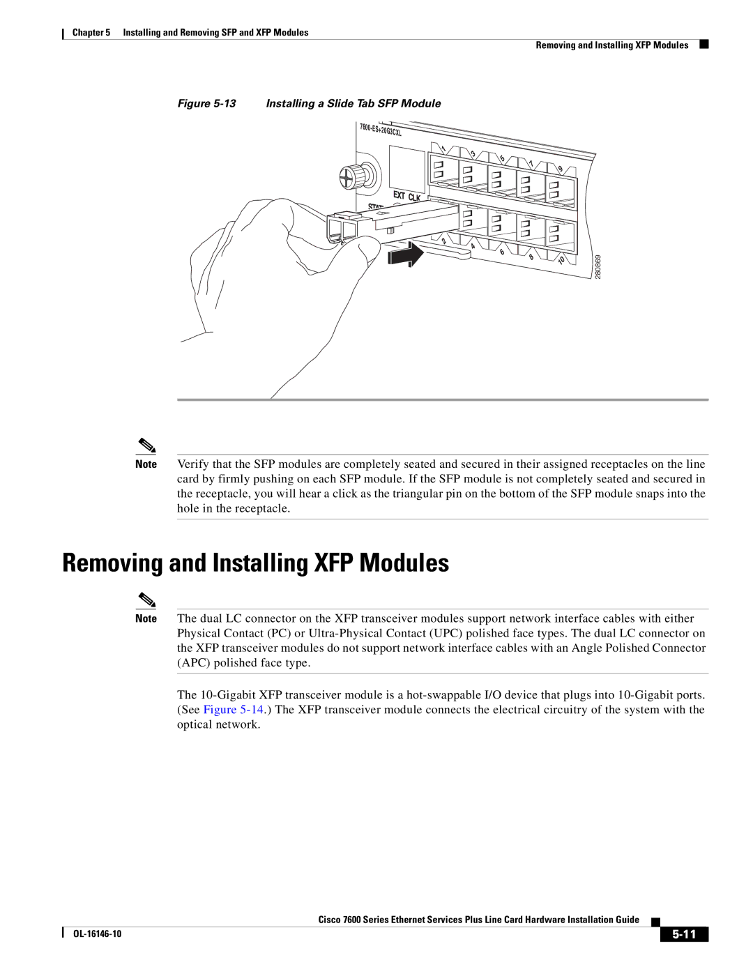
13 Installing a Slide Tab SFP Module
Removing and Installing XFP Modules
14 10-Gigabit XFP Transceiver Module
Installing the 10-Gigabit XFP Transceiver Module
Installing the 10-Gigabit XFP Transceiver Module
If you are removing an XFP transceiver, follow these steps
Removing the 10-Gigabit XFP Transceiver Module
17 Removing the 10-Gigabit XFP Transceiver
OL-16146-10
Troubleshooting Installation Issues
Troubleshooting
1provides solutions for troubleshooting line card issues
Troubleshooting Line Card Power Issues
Problem Solution
Miscellaneous Line Card Issues
Show power and dir sup-microcode
Execute the show scp status and show scp
Line cards. If no response is received after three
Troubleshooting ES Plus Line Card States
Using debug Commands
Packing a Cisco 7600 ES+ Line Card for Shipment