Product Descriptions
What Is the Cisco 7010?
The Cisco 7010 is a
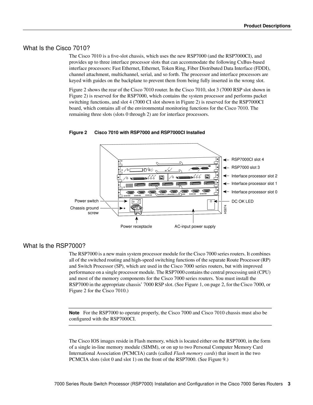
Figure 2 shows the rear of the Cisco 7010 router. In the Cisco 7010, slot 3 (7000 RSP slot shown in Figure 2) is reserved for the RSP7000, which contains the system processor and performs packet switching functions, and slot 4 (7000 CI slot shown in Figure 2) is reserved for the RSP7000CI board, which contains all of the environmental monitoring functions for the Cisco 7010. The remaining three slots (slots 0 through 2) are for interface processors.
Figure 2 Cisco 7010 with RSP7000 and RSP7000CI Installed
Power switch
Chassis ground screw
NORMAL | EJECT | SLOT | 1 |
| CPU | HALT | RESET |
| 0 |
| |||||
| SLOT |
|
|
|
| ||
ENABLE | ENABLE |
|
ROUTE SWITCH PROCESSOR![]()
. | CONSOLE |
AUX | |
|
RSP7000CI slot 4
RSP7000 slot 3
Interface processor slot 2
Interface processor slot 1
Interface processor slot 0
DC OK LED
H5874
Power receptacle |
What Is the RSP7000?
The RSP7000 is a new main system processor module for the Cisco 7000 series routers. It combines all of the switched routing and
Note For the RSP7000 to operate properly, the Cisco 7000 and Cisco 7010 chassis must also be configured with the RSP7000CI.
The Cisco IOS images reside in Flash memory, which is located either on the RSP7000, in the form of a single
7000 Series Route Switch Processor (RSP7000) Installation and Configuration in the Cisco 7000 Series Routers 3